After reading through all logs of David Gönner's relay cock, I made a checklist to see how feasable it would be to do it with the tools of trades I have at my disposal.
Formfactor
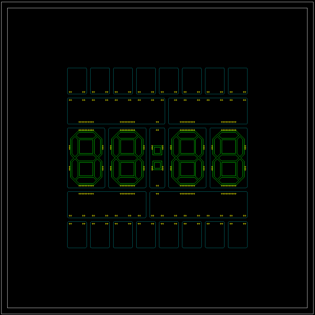
After playing around with the circular design, I replaced it with a Rectangular one - and sticked with it after seeing the advantages. I also found immediately a decent way to put it on the wall: A simple 50x50 frame from Ikea that could hide the extra electronics + wireing that I wanted noone to see. As color I've chosen black PCB's and white LEDs.
The first step was designed with LibreCAD and OpenScad. The outer size requirement of 30x30cm and the gaps defined by the pinheaders as connectors gave me the required sizes for all PCB's.
Schematic / Module Design
 Since I planned to order a minimum of PCB designs (price!), I needed to develop even the modules modular, mostly via jumper pads that could be soldered together when needed. I also got rid of the Routing-PCBs and reduced the Signals to a minium.
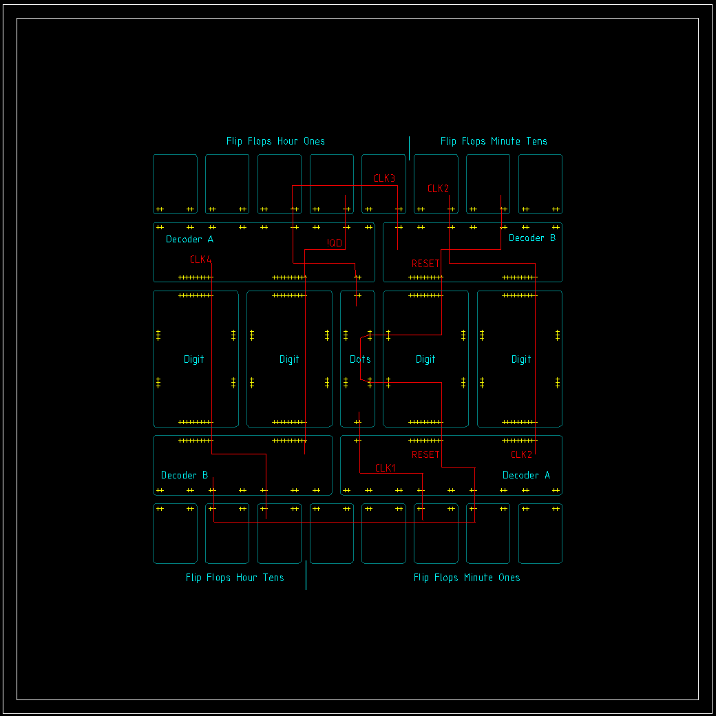
The FlipFlop modules should themselves be capable to build the beginning, the middle section and the end of a Johnson Counter. They also needed to provide access to the relay line, their inverted output signal or even the common clock signal via the configurable output pin. The schematic of the FlipFlop is schamelessly based on the original design - which was already a copy of another design already.
The decoders needed some changes from the original design. I decided to place a "A&!B" Gate on each Decoder. One is needed for the reset (tens, hours) and the other three for monoflops to generate a short puls out of the rising flank of the most significant FlipFlop Output.
Signals

All in all I could also reduce the signals that needed to be piped from top to bottom or from bottom to top down to four: Clk2 (Minute, tens), Clk4 (hours, tens), Reset and !QD from the "hours, ones" decoder (needed for reset condition). To achieve this, I just added a generic "pipe" signal to every digit.
The "dots"-module in the center got all the features that were necessary to set/reset the clock via an external micro controller. I chose the relays as "level shifters" to not break with the design concept. An nfet would have done the job as well, but what the heck. Two buttons got added as well to clock the minutes or hours up for the debugging. The dots themselves can be also controlled via the controller for debugging / connection info, but later more to that.
Digits
Seven Segment Digits were to way to go. But how? The required size can only be done custom and a multitude of leds like David did in his project is too power hungry for my taste. My first idea was to 3D-Print the frame of the segments and then to fill it with hot glue as a diffusor. The problem to that is simple: HEAT. The Frame will in the best case just bend and ruin the shape. So I had the idea to make a "mold" based on stacked PCBs to form the segments. The diffusor tests with the chosen LEDs and distances was promising. So lets wait and see if my mold works as good as it sounds.
Project Status
My PCB orders are dropping in one by one now and the Project logs will mainly be about the "putting stuff together" part. The "DecoderA" is already lying next to me - working. One Module down, 4 to go...
 SwiftyTheFox001
Discussions
Become a Hackaday.io Member
Create an account to leave a comment. Already have an account? Log In.