 Paul Kocyla
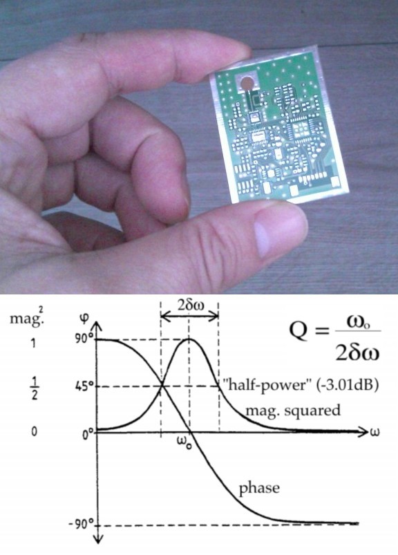
Finally the new driver board arrived. Like mentioned before, it is intended to work as a vector network analyzer (VNA) beside its function as 24 GHz RF power source.
It should be able to measure the power reflected from the cavity in phase and magnitude to tune into resonance frequency and even calculate the Q factor.
Look at the chart to see how phase and magnitude behave below/in/above resonance frequency.
However, it is my first try in directional coupling and microwave power measurement techniques, so I don´t know how good it will work.
Further improvements to the last system:
- PA current sensing done via a shunt instead of a hall sensor (which was not very accurate)
- PA biasing improved
- New silver cavity designed for TE013 mode @ 24.1 GHz
Discussions
Become a Hackaday.io Member
Create an account to leave a comment. Already have an account? Log In.
Nice board! I've got three questions about it: What board material is it made from? Where did you get it made? How much was it? Thanks!
Are you sure? yes | no
Standard 4 layer FR4, made by a german PCB manufacturer, they got a minimum area of 160x100 mm2 for about 60€+tax
Tried to match the microstrip to this layer setup, but can´t say how well I did it, a test will show.
Are you sure? yes | no
Thanks for the reply! Ahh yes, microstrip design brings back memories of college days, although I've never had to do it since. I was looking into creating my own RF source kinda like yours but only up to around 5GHz. I had read that anything above 3GHz needs to use something other than FR4 since it becomes "too lossy." I had been looking for a cheap place to do Rogers 4000 series material but they're all pretty expensive (at least compared to traditional FR4). I'm eager to see how your board works out; hopefully it's just fine with the FR4 material.
Anyway good luck and I'm excited to continue reading about your experiment!
Are you sure? yes | no
What are the dimensions of your new cavity?
Are you sure? yes | no
From the previous log entry:
Diameters 29.5mm/16mm, length 27.5mm, f=24100 MHz
I´ll use the mode TE013 because others already had good test results with this mode.
I'm trying to find the resonance modes of this cavity too, but am not really succeeding yet (due to my inability for sure). I'm quite curious to find out if this source can tune in to those itself, would be quite awesome!
Are you sure? yes | no
I may be able to help in some way. I am currently running FEKO simulations for all manner of EM drive frustums. Have a look in /r/emdrive on Reddit.
I will be able to find the resonant freqs. and modes that you need and then your board can fine tune to your actual frustum in real-time.
I am very skeptical that you get any anomalous force from these things, but it is all good fun.
Good luck!
Are you sure? yes | no
I see your question has been answered already. Sorry, I am a bit lazy in answering at the moment.
I´ll take a look on your reddit posts. Currently I used Traveller´s spreadsheet to get the resonance check for the cavity.
I´ll make the fine tuning by checking the phase of the reflected wave - hope this will work.
Are you sure? yes | no
Feko can supply phase info for the reflected wave. I can generate polar or Smith charts with phase info. Maybe that would be very useful to you.
Are you sure? yes | no
Thanx a lot. I am using just one antenna for RX and TX and couple out the reflected wave. In resonance the phase should be zero (relatively). However, I expect some side effects from eventual bad coupling and eventual bad impedance matching.
I designed the cavity for TE013 with f0=24100 MHz, but it would be good to know if there are other modes within the transmitters range.
Maybe there´s something you could help me with, and the whole community:
Can you simulate the antenna position? It would be very interesting to find the optimal injection point. I am using a lambda/4 antenna.
There´s not much information about antenna placements in emdrives on the web.
Are you sure? yes | no
I've just posted more Feko sims on /r/emdrive. They confirm the presence of TE013 and other modes. Dr Rodal on NSF thinks the sims are now useful for 'real' EM drives. I can put any type of antenna anywhere in the frustum and excite it with any freq. A 1/4 wave stub antenna is the simplest. Feko will also calculate all the S-Parameters, like impedance, mismatch loss, reflection coefficient, VSWR etc
Are you sure? yes | no
Cool, great job!!
I put the antenna hole on the sidewall, about lambda/4 distance from the big end.
But it´s no problem to close the hole and to drill another one.
Could you simulate several positions for 24100 MHz along the sidewall for a 1/4 stub?
I would take the position with best results for the experiments.
I´m really happy to hear that your simulation model works and hope to hear from you soon.
Are you sure? yes | no
Nice! On r/emdrive I could only find FEKO simulations of around 2.4 GHz. Are you also planning to run simulations of the cavity described in this log?
Using Greg Egans exact solution (mentioned in Rodal's link) to the Maxwell equations I get a TE013 mode that is quite off:
TM010: 9.79 GHz
TM011: 14.6 GHz
TM012: 19.5 GHz
TM013: 24.4 Ghz
TE010: 16.7 GHz
TE011: 20.2 GHz
TE012: 23.8 GHz
TE013: 27.8 GHz
Do you get similar resonances?
Are you sure? yes | no