 Paul Kocyla
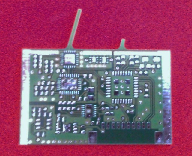
It arrived. The PCB has two antennas. The big one is the probe for feeding the cavity and the small one is for feedback RX.
We will try to make the antenna position variable inside the cavity.
About the RF source: A VCO transceiver is controlled with a 16bit DACs The TX frequency is divided by 16*65536 and fed back to the controller. The I component of the RX baseband is fed into the ADC input of the controller.
A 500mW amplifier is connected to the transceiver´s RF output and fed with 5V. A negative bias for the amplifier is generated by a charge pump from another DAC.
The feedback antenna is shortened for not stealing much energy out of the cavity. It is attenuated by 40dB before going back to the transceiver IC.
Discussions
Become a Hackaday.io Member
Create an account to leave a comment. Already have an account? Log In.