 Paul Kocyla
To avoid confusion, here are some explanations regarding the measuring procedure, the software and the orientation of the cavity:
Here is the top view of the setup I will refer to from now on.
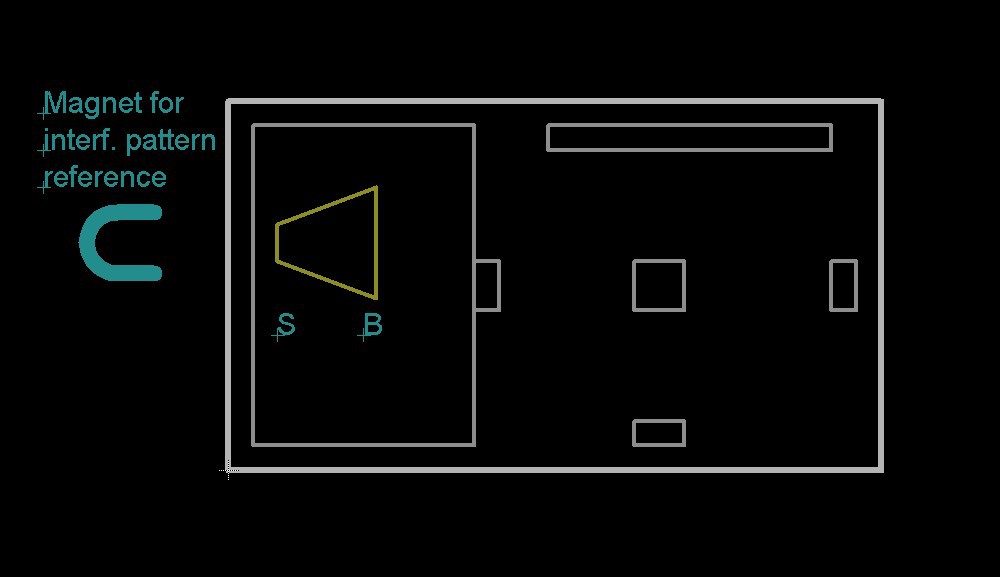
When I refer to the cavity orientation as "SB", it means that the "S"mall end is on the left and the "B"ig end on the right, "BS" is the other way around.
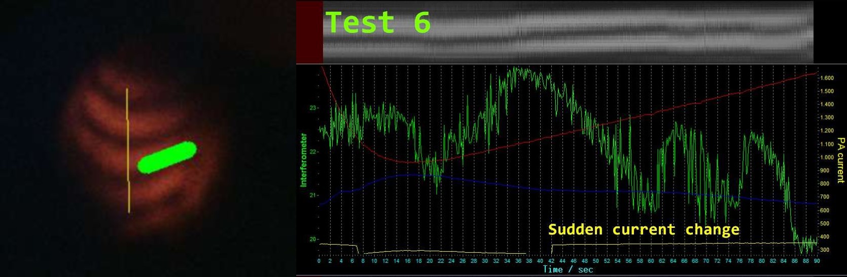
Here´s how the chart works:
- On the left side is the camera image of the interference pattern. The grey graph is a continous sampling of the yellow line in the interference image, so if the pattern moves up, the grey graph also moves up.
- The green graph is just the pixel brightness sum within the thick green line in the interference image. It will generate a more or less sinusoidal wave over time when the pattern is moving continously. However, it will not tell you the direction in which the interference patern is moving, but it might be helpful to make small changes more visible.
- After having adjusted the mirror to get a good interference pattern, it´s not clear in which direction the pattern will move in respect to the force.
I use a magnet to determine that. My reference will be "U" if the rings of the pattern go up and "D" if they go down while attracting the platform with the magnet.
Discussions
Become a Hackaday.io Member
Create an account to leave a comment. Already have an account? Log In.