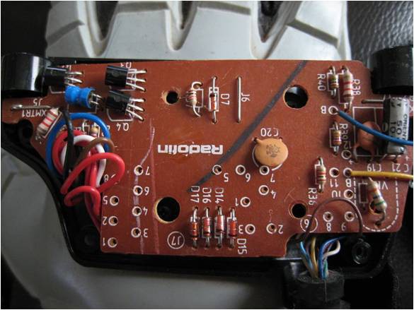
Opened wrist unit, top of board
 http://www.instructables.com/id/Hacking-a-Powerglove/?ALLSTEPS
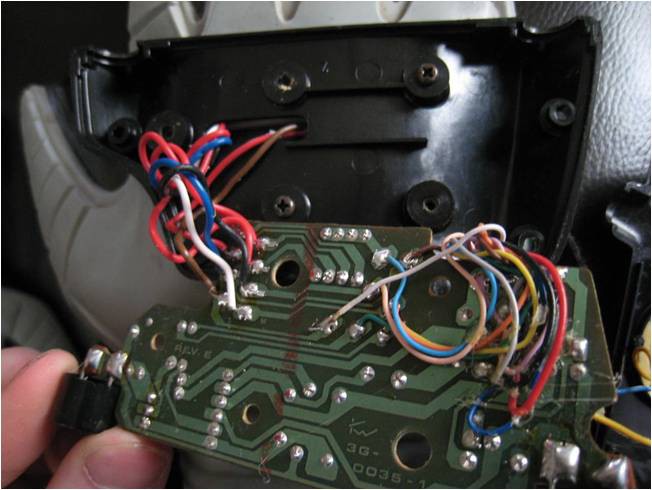
Opened wrist unit, bottom of board
http://www.instructables.com/id/Hacking-a-Powerglove/?ALLSTEPS
The first two images above are taken from that instructable, and they show the stock wrist unit internals.
In the image of the top (brown) of the board, the only parts that I care about are the tight bundle of eight wires on the left side of the image( four red, and four of various colors) and the four brown/copper colored vertical diodes. I replaced those diodes with 10K Resistors as per the instructable to make each of the flex sensors in the fingers act as part of simple voltage dividers. For more information on voltage dividers in this context, please see: http://homepage.cs.uri.edu/faculty/hamel/workshops/as220-sept-09/sensors-voltage-dividers.html
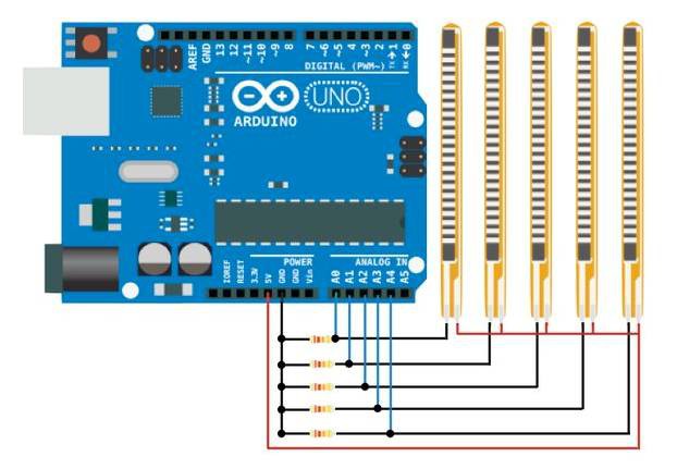
Please see the circuit diagram above for the general idea for wiring to an arduino, from: http://www.instructables.com/id/DIY-Robotic-Hand-Controlled-by-a-Glove-and-Arduino/?ALLSTEPS
Thankfully, the powerglove's wiring color scheme makes ...some sense. One red wire for each bend sensor. There are a bunch of other colors for the remaining wires from the bend sensors. When I initially hooked everything up, I randomly connected them to the arduino.
I was able to see expected output values from the four voltage divider circuits on my arduino that changed as I bent each of the fingers. Now that I was able to confirm the flex sensors worked as expected, it was time to map the changes in output from the arduino's A/D converter to mouse clicks!
Discussions
Become a Hackaday.io Member
Create an account to leave a comment. Already have an account? Log In.