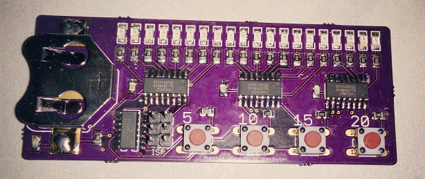
I haven't had time to populate one of the latest PCB's that I received from OSH park a couple of days ago but apparently I wasn't tired tonight so I decided to give it a go. I often tinker at night when I can't sleep since it's quiet, the kids and the animals are sleeping and I know nothing's going to disturb me. I'm sure I'm not alone doing this at night ;)
I haven't done any serious surface mount soldering in a while, and my layout is a bit fiddly, but it's only a prototype and I can correct anything that might be dodgy. Luckily all was fine and a quick test verified that all LEDs were working as well!
Tomorrow I shall flash the bootloader on the ATTINY84 that's the brain of the tool but I shall be a bit more careful this time since last time I flashed a blank ATTINY85 I must've got a fuse wrong since it was impossible to flash it ever again - which was really annoying since it was soldered to the PCB that was prototype v2. I will use the Arduino IDE to flash via ISP this time since that's the planned way for the end-users to do it in case they want to update firmware or customise the tool for a specific need. (or just if they want to tinker!)
Some of the resistors and one cap are a wee bit crooked, but this is a functional test of the design and not the final thing, and I had to hand solder all small components since the solder paste was just too damn cold to use initially. I did however solder the IC's with hot air and solder paste as the last step. In hindsight I should have done so with all components but it doesn't have to be pretty at this stage...

(sorry for potato-cam. better pictures in the future...)
One thing I must remember to the next version is to use surface mount tactile switches. I want the bottom side to be totally flat, and I certainly don't want anything sharp sticking out anywhere... The ISP header will never be populated in the finished product, just there to be added by the end-users if needed.
I do hope my EE-fu has been strong and that my design works as intended because now I want to focus on the code from now on so I can begin usability testing in a month or so...
Happy hacking!
 jens.andree
Discussions
Become a Hackaday.io Member
Create an account to leave a comment. Already have an account? Log In.
You could try to bend the switch pins to fake a smd part and use a different header footprint - there are smd 0.1" footprints with pads and headers with bend legs, too. Good luck with your project! :)
Are you sure? yes | no
Yes, I did think of that but since this is merely a platform for functional tests and hopefully usability testing I decided to run with thru-hole components for the tactical switches since I have yet to find the "correct" ones. I will order a bunch of different membrane switches and give them a go. Most of the really young autistic kids have lack of fine motor skills so the buttons must be simple to press, but yet distinct and provide adequate feedback - either via "click" or sensed. This however is not critical at this stage and I ran with what I had plenty of...
The ISP header will not be populated on the final version but since this board will be flashed often I put it on there for simplicity!
Thanks for your kind comment! :)
Are you sure? yes | no