-
1Step 1
Let's Build a Power Supply
These instructions will guide you from beginning to end. If anything is unclear, let me know in the comments section.
You will be able to build this power supply, even if you've never soldered anything before in your life.
Now let's start with some basics:
Before You Begin
- Soldering the power supply should take about an hour or less.
- Make sure you have enough time, and an environment without distractions. Don't stress, just enjoy building.
- Take the time to read and understand the instructions.
- Make sure you understand each step. If not, read again or ask a question in the comments section.
- Notice that many components must be oriented a certain way.
- Clicking on a picture will bring up a high resolution version. Use this to make sure your components are placed right.
How to Solder
If you're just starting out soldering, or if you need an update on how to solder,SparkFun has a great tutorial for soldering through-hole components.
If you have never soldered before, I strongly recommend these two videos from EEVBlog:
-
2Step 2
Required Components
To build the Muffsy Hifi Dual Power Supply, you need:
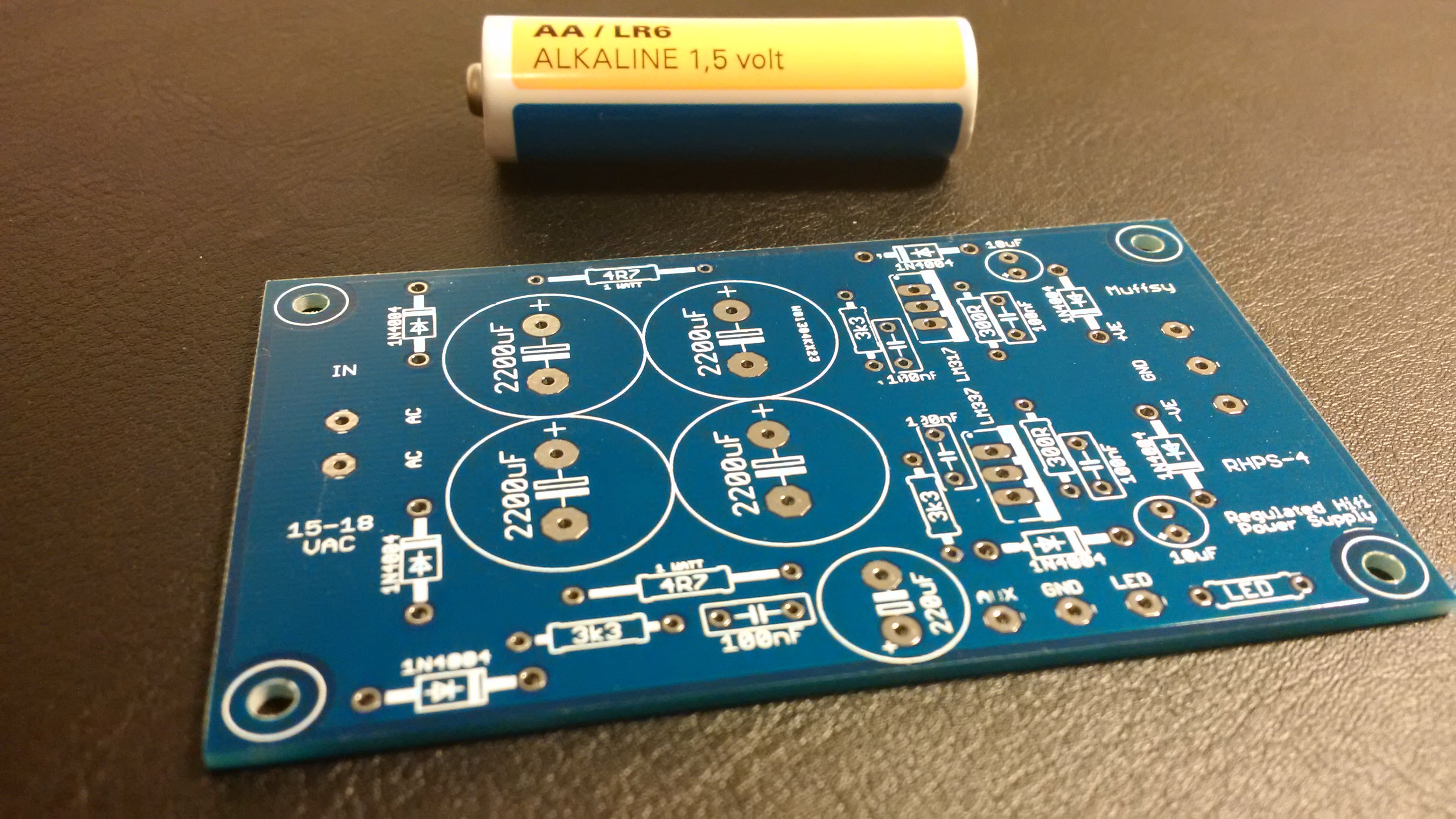
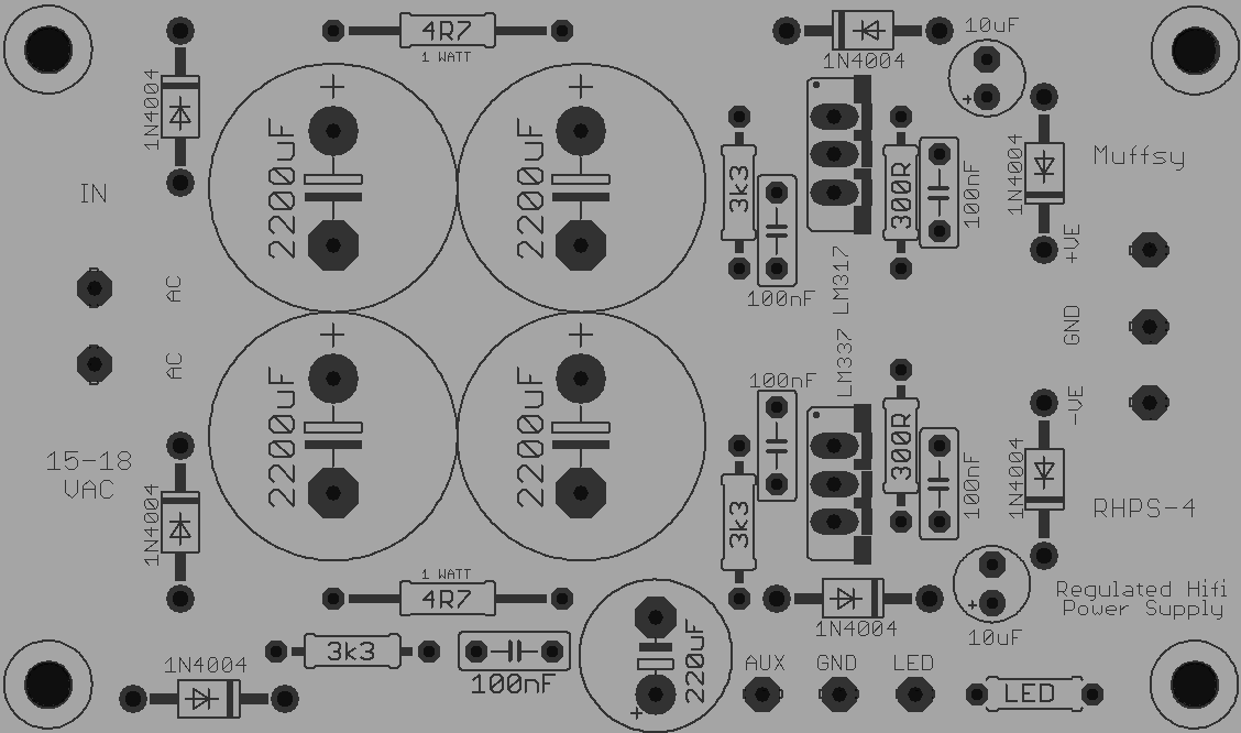
- The PCB
- Components, from the list of components
![]()
![]()
-
3Step 3
Diodes
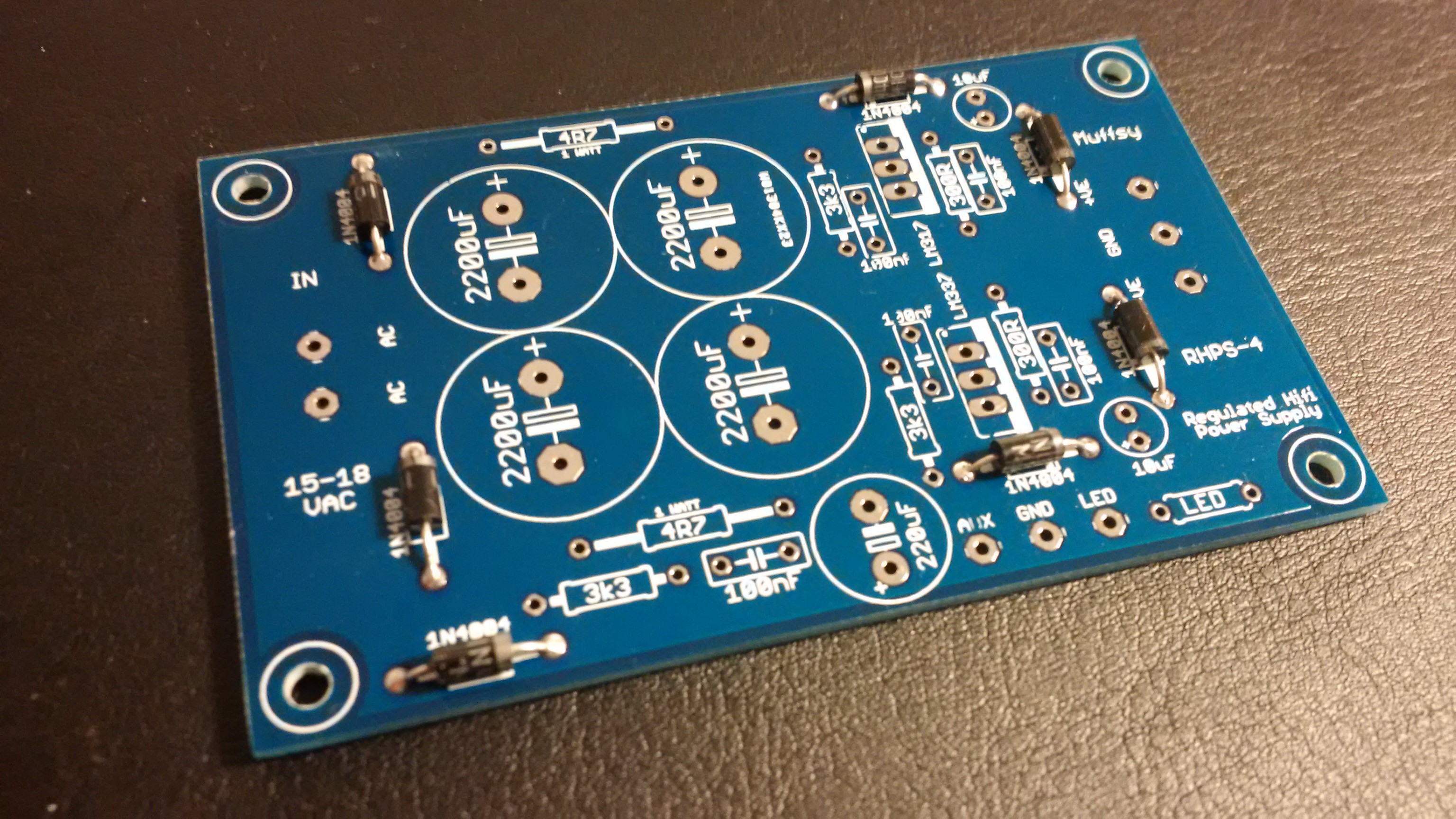
Start by soldering the seven diodes:
![]()
Make absolutely sure that they are oriented the right way around. The silver ring on one end of the diode corresponds with the white band of the diode symbol on the PCB.
-
4Step 4
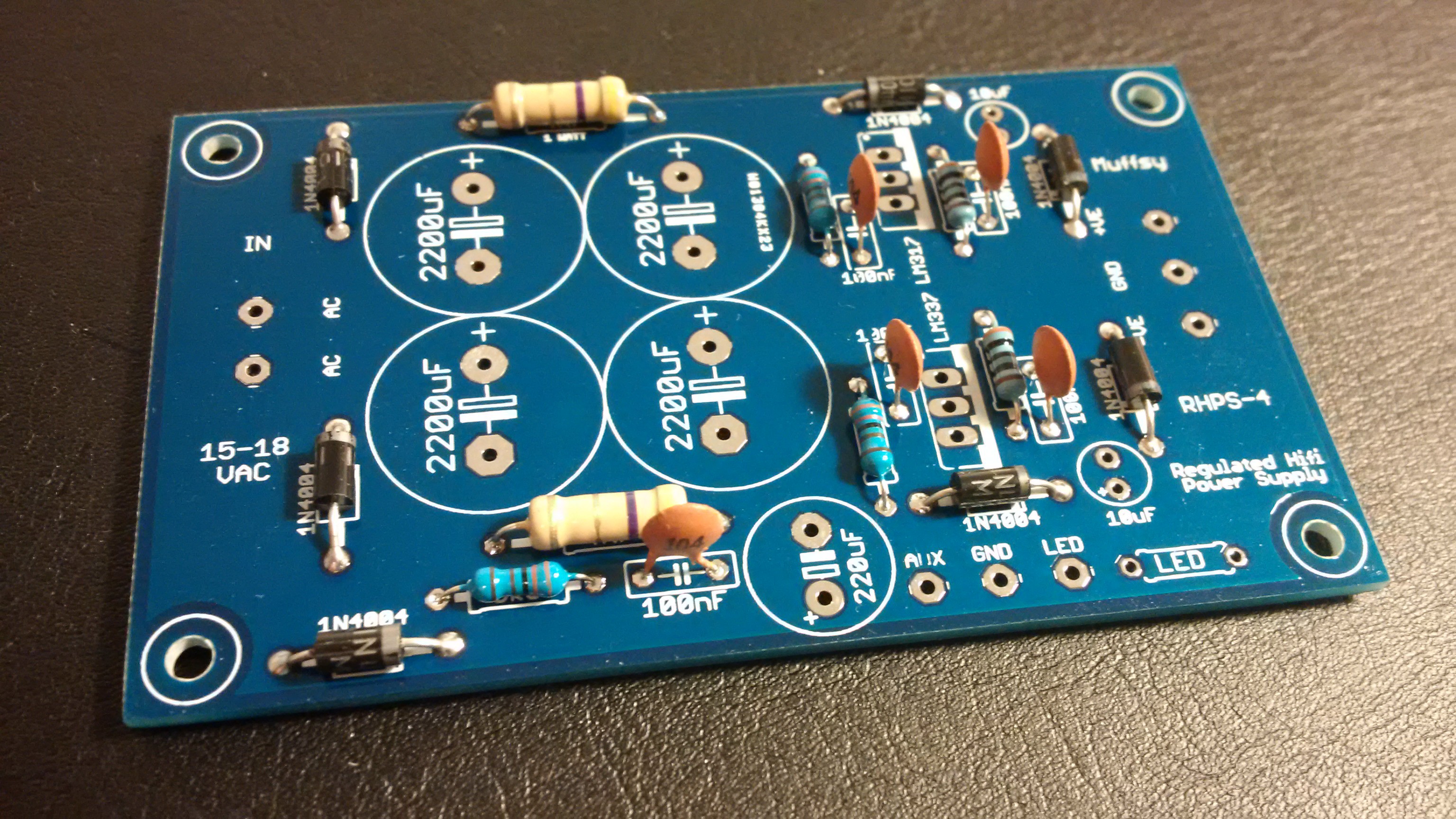
Resistors - 0.25W
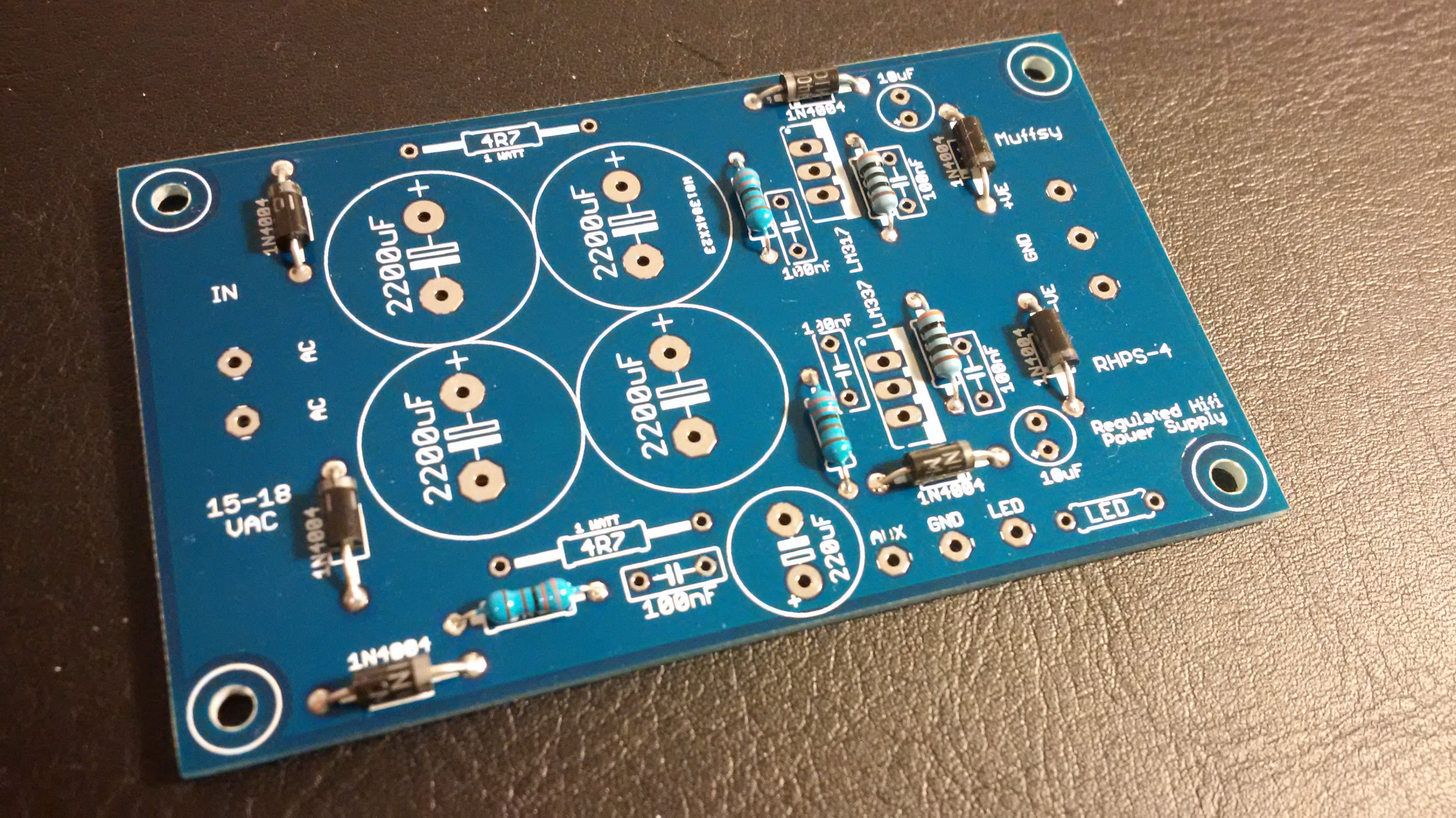
Next, solder the five 0.25W resistors:
![]()
Orientation doesn't matter here, I like to put equal values the same way because I think it looks nicer.
-
5Step 5
Resistors - 1W and Ceramic Capacitors
Solder the two 1W resistors and the five 100 nF ceramic capacitors:
![]()
Again, orientation is not important for other than aesthetic reasons.
-
6Step 6
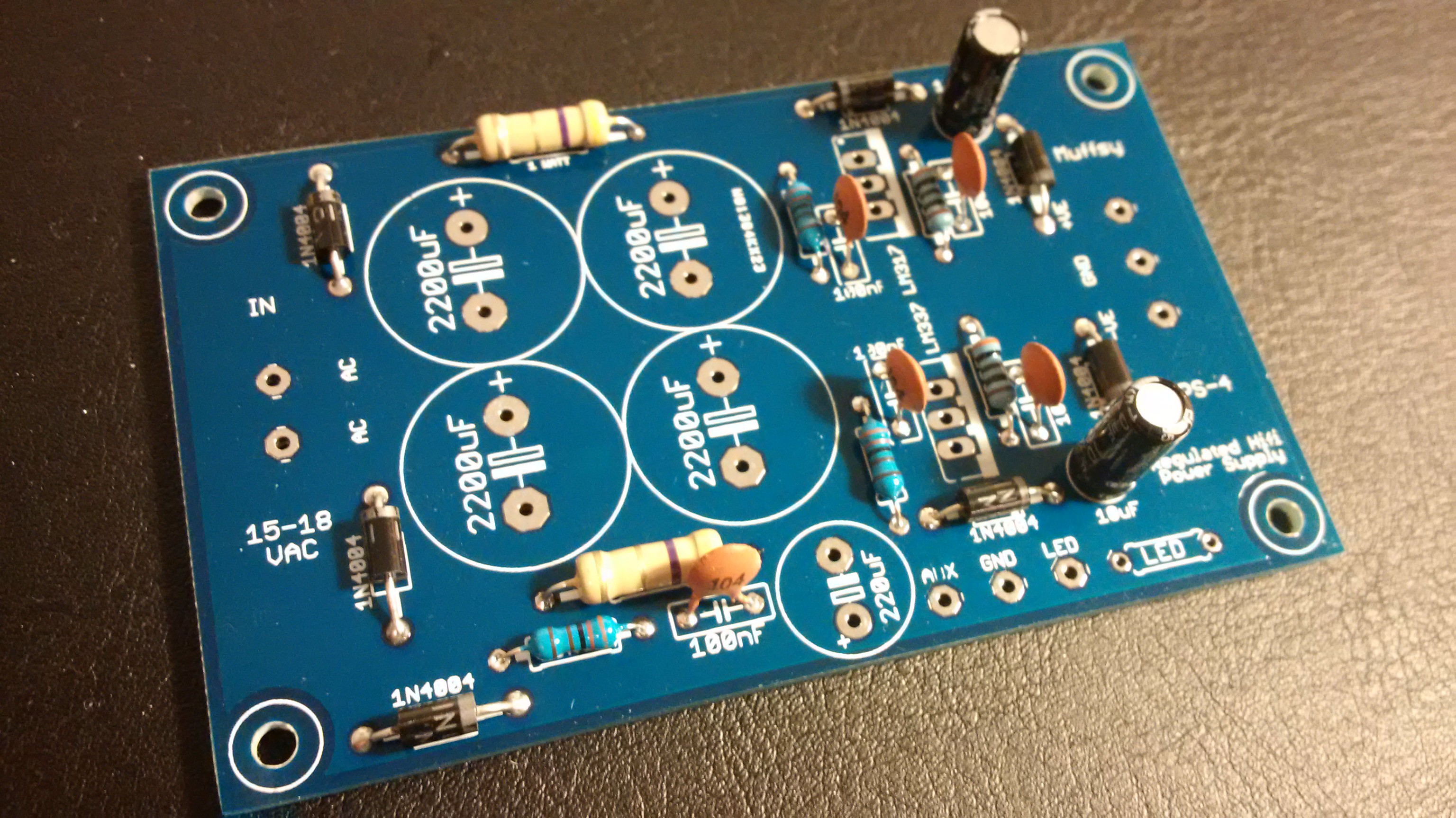
10 uF Electrolytic Capacitors
Solder the two 10 uF electrolytic capacitors:
![]()
Make sure that the white band on both capacitors (marking the negative lead) is pointing upwards when the text on the PCB is oriented the right way.
-
7Step 7
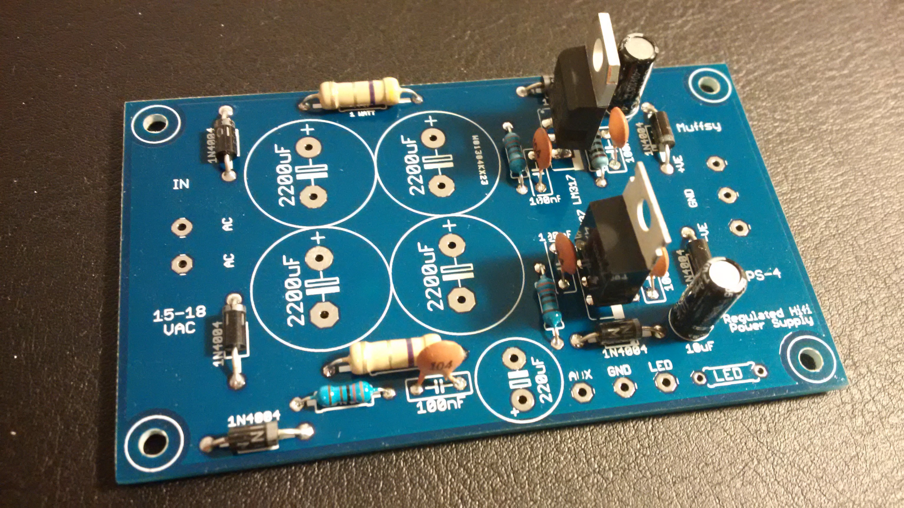
Voltage Regulators
Solder the LM317T and the LM337T voltage regulators. Add heat sinks if you need more than 100 mA output:
![]()
In this picture, the LM317T is the one furthest up. Make sure that you place them the same way as on this picture, or your PSU will not work.
-
8Step 8
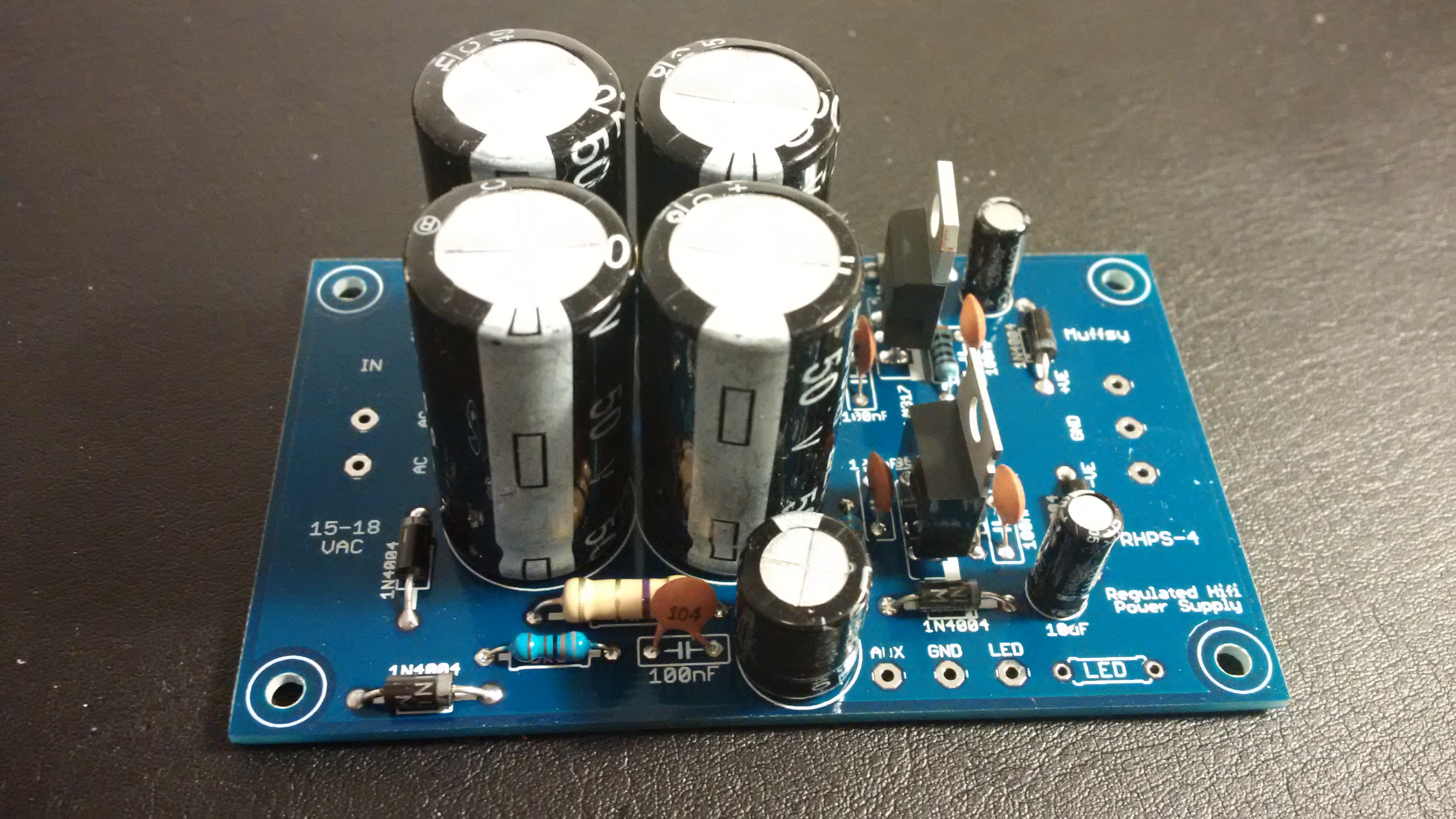
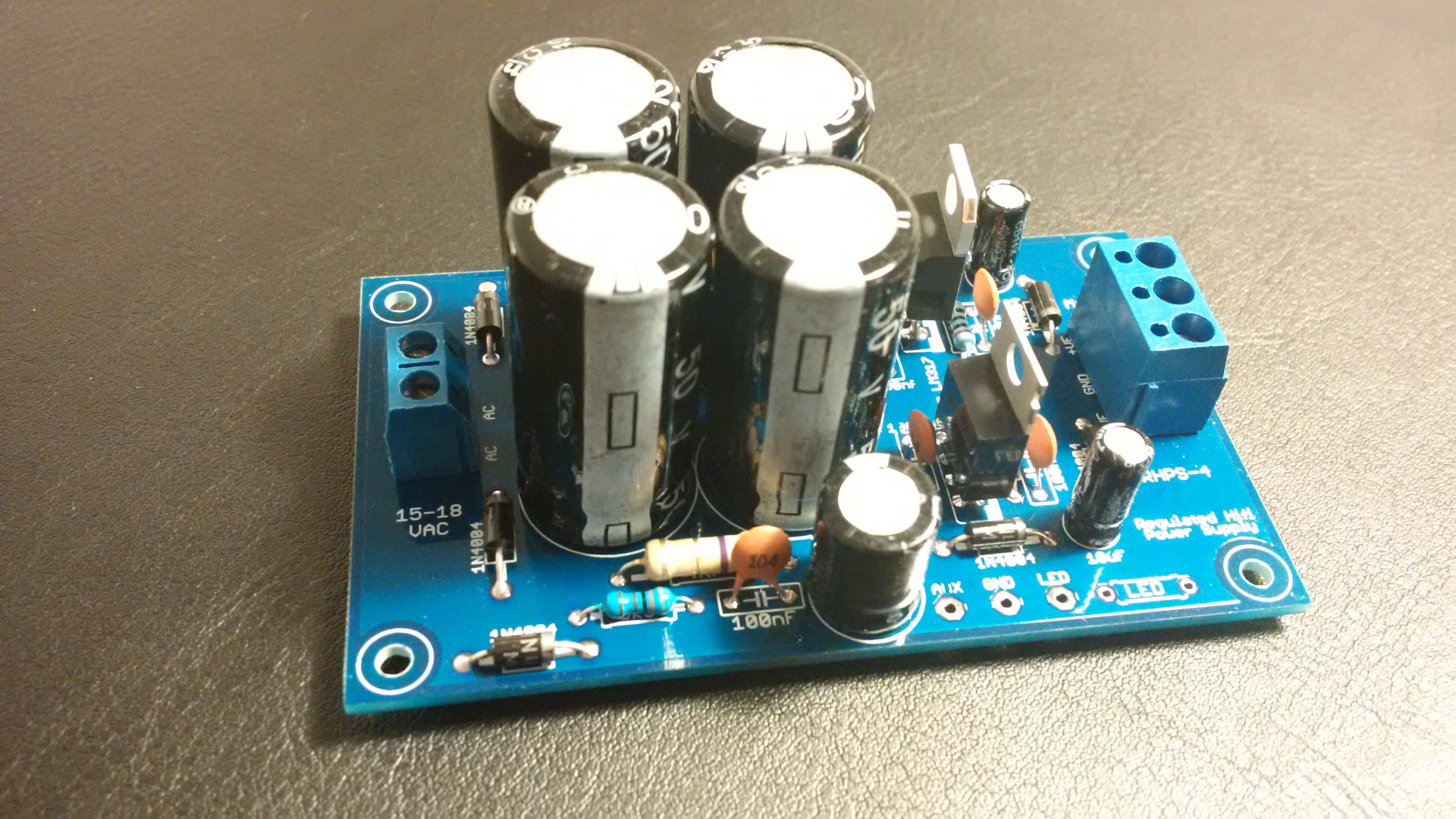
2200 uF and 220 uF Electrolytic Capacitors
Solder the one 220 uF electrolytic capacitor and the four 2200 uF electrolytic capacitors:
![]()
The white bands (negative side) of all four larger capacitors are pointing downwards, while the white band on the smaller capacitor is pointing upwards.
-
9Step 9
Terminal Blocks
Solder terminal blocks if desired:
![]()
-
10Step 10
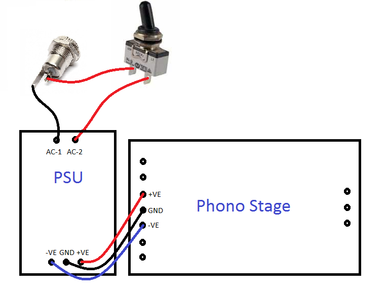
Hooking Up, and Power Switch
Here's how to use the PSU with the Muffsy Phono Stage, complete with power switch:
![]()
AC Input
Notice that the power from your wall adapter goes in at the top, marked AC-1 and AC-2. (The print on the PCB actually says AC and AC). Which cable from the wall adapter that goes to which of the two AC inputs is of no consequence.
DC Output
The output, -VE/GND/+VE, goes to the equipment you want to power. In this case, my phono stage.
Power Switch
Notice that you only have to use the power switch to cut one of the AC connections. This will break the circuit, and power off the PSU.
A SPST (Single Pole Single Throw) power switch is recommended. If you get a push-button power switch, make sure you get the latching kind which stays in place when you push it in.
PLEASE NOTE:
The 2.1mm power connector must be completely isolated from the chassis, as both connections carry electricity!
Discussions
Become a Hackaday.io Member
Create an account to leave a comment. Already have an account? Log In.