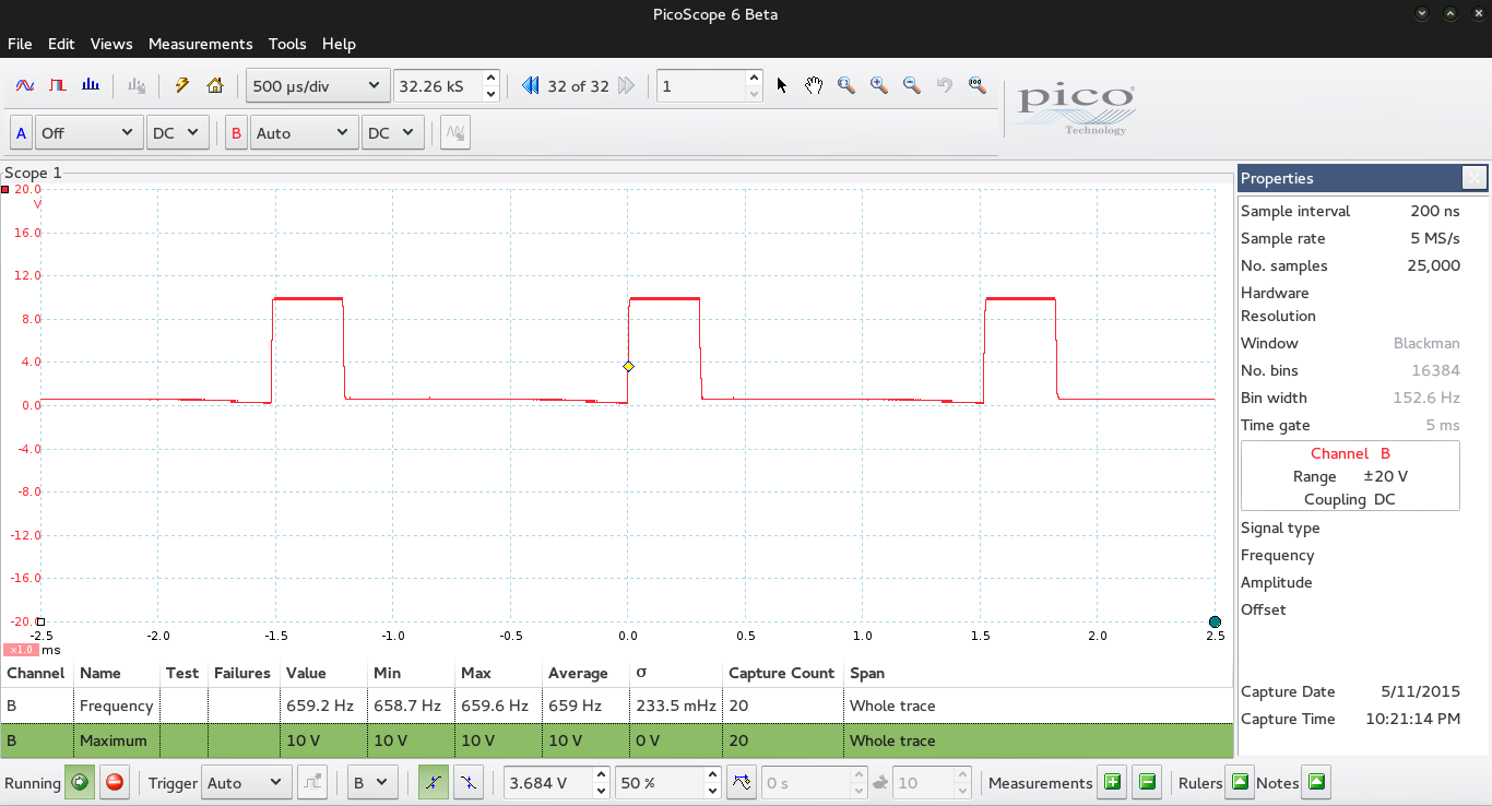
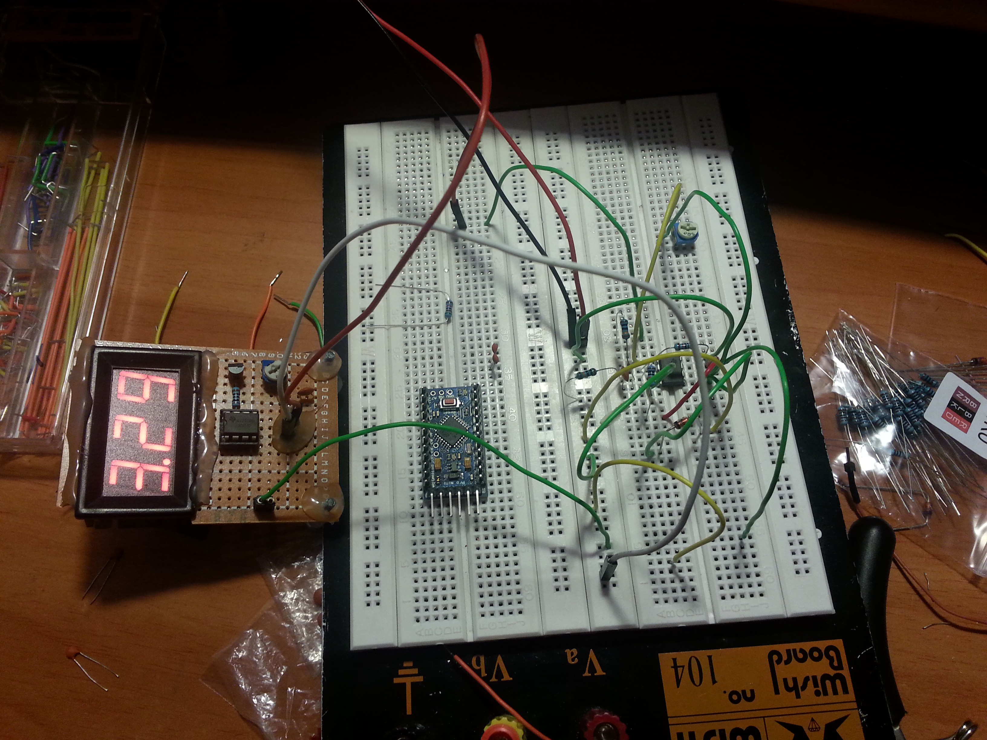
As expected, practice is different from theory and simulation. The calculated frequency that circuit should give at 3.3 volts is 655 Hz, the real frequency, as shown by a very cheap PC based oscilloscope is 660 Hz and by a Fluke 177 multimeter 681 Hz. If we take the first value, 660 Hz, we're not too far from 655 Hz which looks actually promising. Note that the maximum voltage is exactly 10V. The frequency is a bit bigger than expected, which seems wrong, because a resistance (for example the output resistance of the LM358) should lower that frequency. Something else must be there, I will check. I'll have to search for a good oscilloscope at my university and measure that frequency again.

Anyways, I have a plan to correct/solve this error. First I need to make a simple frequency counter on my Arduino, since that's what I'm gonna use in my power supply. Then I will make about 100 measurements at different well known input voltages (from 1 to 12V) and note the frequencies at those voltages. Then I'm gonna plot those points in QtiPlot or Matlab and do a polynomial interpolation on them to get the function that describes these points. After that I can just use this function to determine the frequency with relationship to the voltage, or use it to determine some kind of equation to describe the error for the formula I calculated.
I'll also try to do some improvements to the circuit so as to minimize any quantity that could have an unwanted effect on the output frequency. I'm also thinking about limiting the minimum output voltage of the circuit, as I saw on my crappy oscilloscope (which I don't really trust) that it gets below 0V, which doesn't seem logical to me. If I manage to do that I can skip the interpolation part and make a circuit that will work even if I change the resistances.

Discussions
Become a Hackaday.io Member
Create an account to leave a comment. Already have an account? Log In.