 Marc Schömann
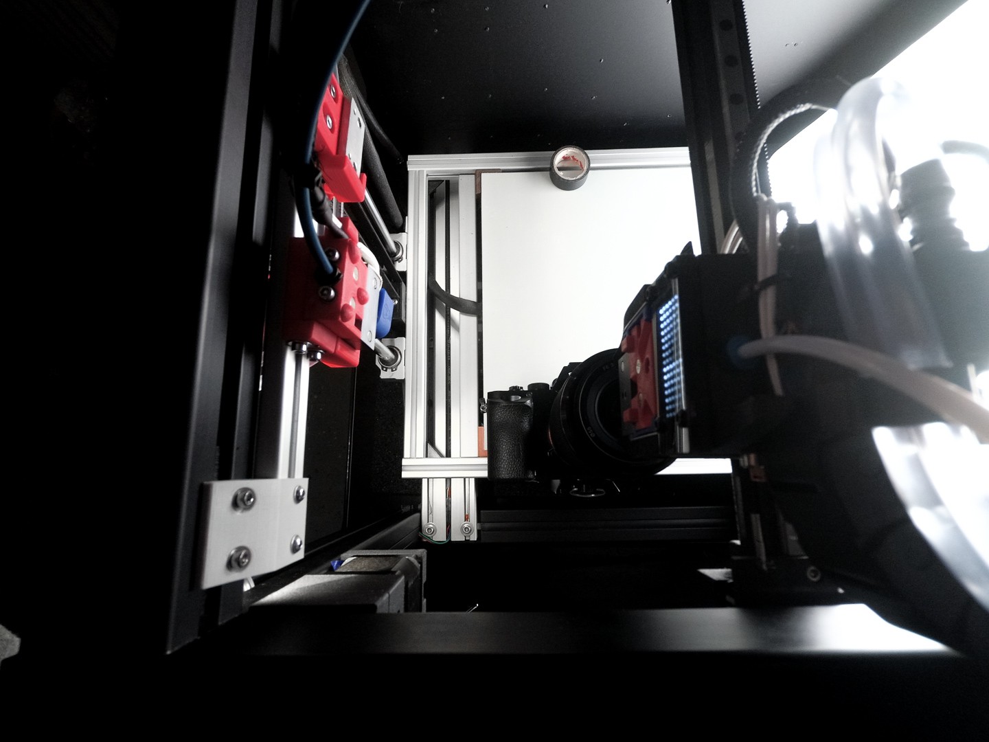
After upgrading the Blackbox with a tool changer, i had to find a way to calibrate the different hotends. The required precision cannot be achieved with mechanical measuring methods. I got inspired doing it optically by a forum post at 3d-druck-community.de Instead of taking a cheap USB microscope I used my mirrorless camera with the kit lens and macro rings. These rings are pretty bad for Makro photos because of the edge blur, but in this case, only the center has to be sharp. So macro rings will do fine for this job and the image quality is even superior to a cheap microscope.
The camera is mounted to the frame, that way you can use the Z-Axis to adjust the focus. I wrote a short script which changes the tool head and returns to a reference point in between.
Test routine G-Code
G21 ;metric values
G90 ;absolute positioning
G28 x; home X
G28 y; home Y
G28 Z; home Z
SET_PIN PIN=BEEPER_pin VALUE=120; short beep for start of the procedure
G4 P100
SET_PIN PIN=BEEPER_pin VALUE=0
G1 Y25 F5000; drive to save position
G1 X15.90 Y112.3 F5000; drive to calibration point
G1 Z224.50 F500; lift z-axis to desired height
T0; switch to tool 0
G1 Z224.50 F500
G1 X15.90 Y112.3 F5000; drive to calibration point
SET_PIN PIN=BEEPER_pin VALUE=80
G4 P2500
SET_PIN PIN=BEEPER_pin VALUE=0
G4 P500
T1; switch to tool 1
G1 Z224.50 F500
G1 X15.90 Y112.3 F5000; drive to calibration point
SET_PIN PIN=BEEPER_pin VALUE=80
G4 P2500
SET_PIN PIN=BEEPER_pin VALUE=0
G4 P500
To simplify the analysis process, I wrote a simple grasshopper script. This script calculates the distance between the tools (toolhead offset). On the other hand, it calculates the deviation between extruder changes, which reveals how exact the tool change process actually is.
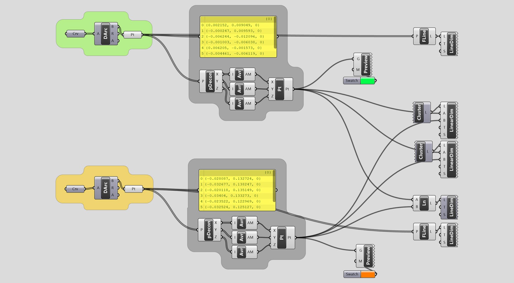
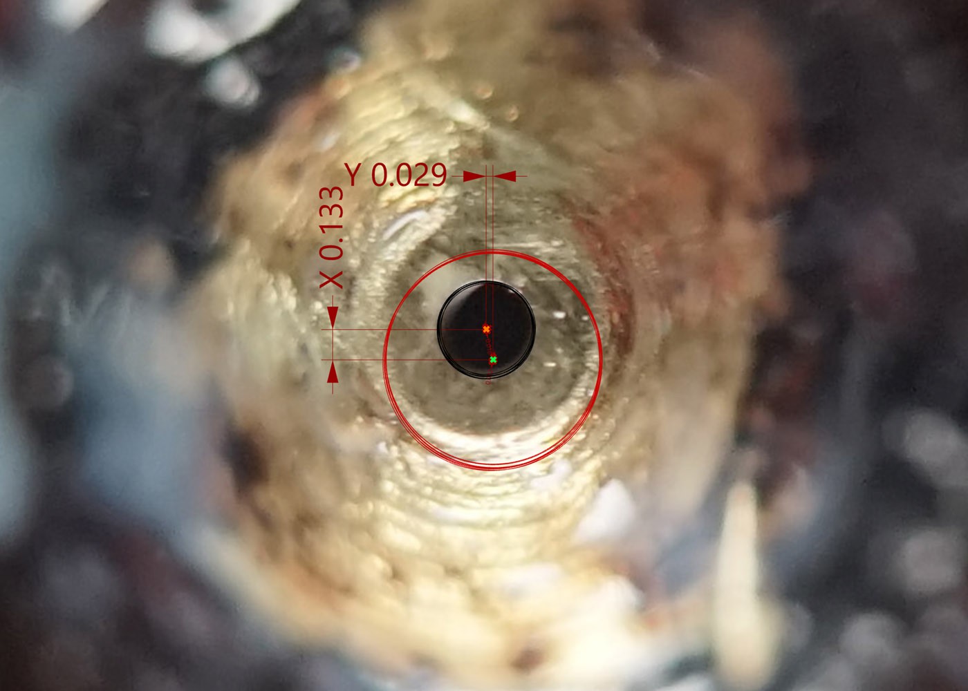
It calculates tool Offset
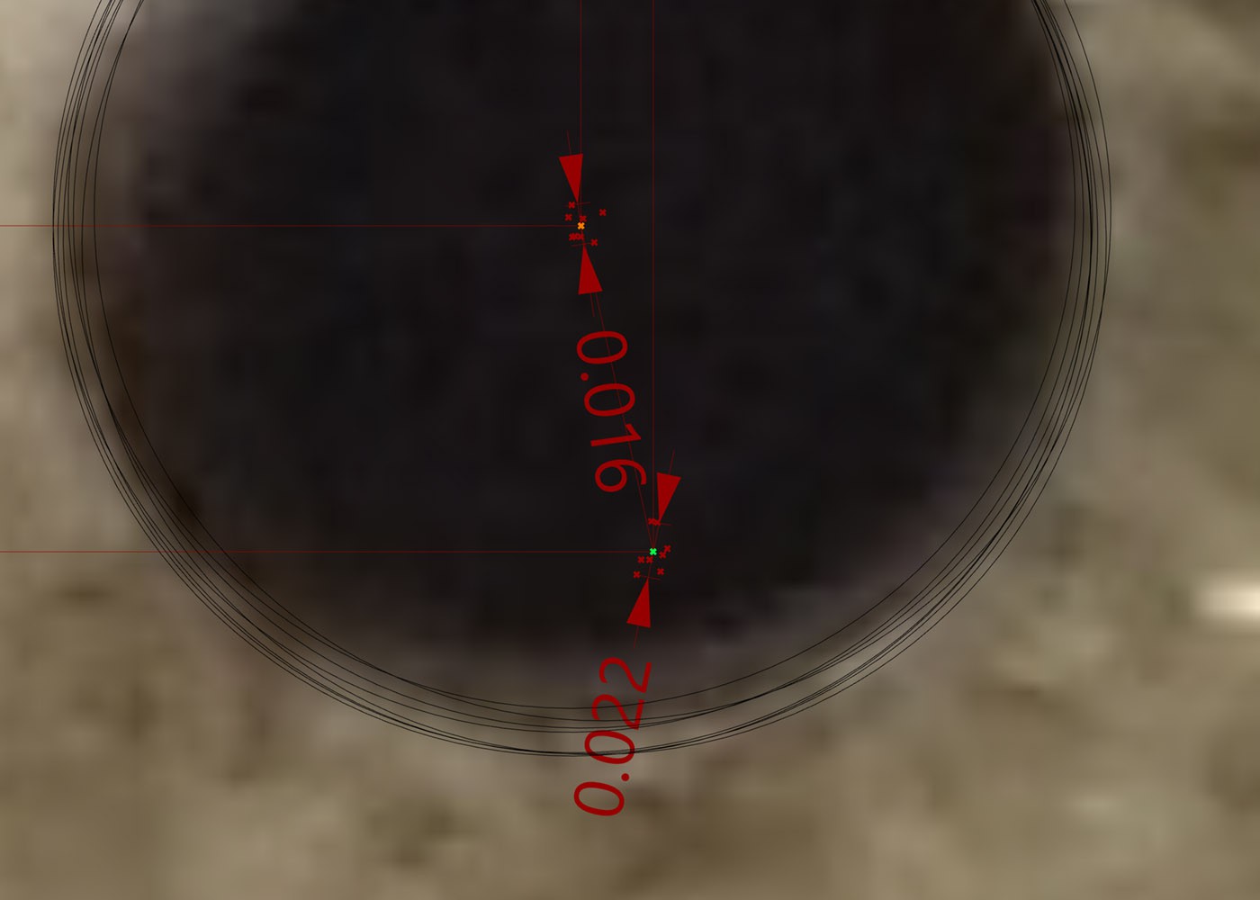
as well as deviation
Buttom Line
As the measurements show, the deviation during tool change is tiny at max. 22 microns. Especially concerning the 16 Mikron deviation of tool 01 (permanently mounted). The measurements from tool 0 to tool 1 differ by only 6 microns. I am very happy and confident about this result regarding further developments. The remaining variance is probably due to inadequate measuring methods and general printer tolerances.
Discussions
Become a Hackaday.io Member
Create an account to leave a comment. Already have an account? Log In.