William
-
Revision Updates & New Parts of the Spec
08/17/2015 at 06:57 • 0 commentsAfter the Maker Fair 2015 revisions were adopted, I went back to work updating a bunch of Retro Modules which were no longer in compliance. This is one of the reasons I'm striving toward a stable pin specification in short order. It is not fun looking at a box full of no-longer-compliant modules. I've had to sift through existing modules to find the few which were not affected by the spec revisions. Thankfully, I am gaining momentum again.
When I built out the hardware for my 'Christmas Truck' project, I used the Retro Modules spec extensively. Those modules will need slight updates now, but even the basic modularity of the install proved useful. I recently traded my truck in for another, and the uninstall process was a breeze. That is -- everything except some of the oldest modifications I made to the truck. The 2012 Tacoma features a LCD screen in the rear-view mirror. It, at times, displays composite video from the stock rear-view camera. I wanted a way to send my own video to the mirror without making a big mess of the mirror housing. I was able to locate the video cable & make a splice quite some time ago. To undo this splice, I had to break out the soldering iron & solder the short segment of wire back together. If I decide to do a similar modification today, I would make it easy to remove any mods. How? I would add connectors (blade, etc) which allow the stock cable to be reconnected to itself with ease. This can increase the cost of the mod, but not by much.Headers
I have spent some more time fleshing out pin header specs & documentation. The very common 26 pin header is hardware compatible with a 25 pin DB-25 connector. The 10 pin header is compatible with the DE-9 connector. This allows the use of old-fashioned header-to-connector ribbon cables. You may have had some of these cables in an older desktop tower.
"AC'97"/"HD Audio"
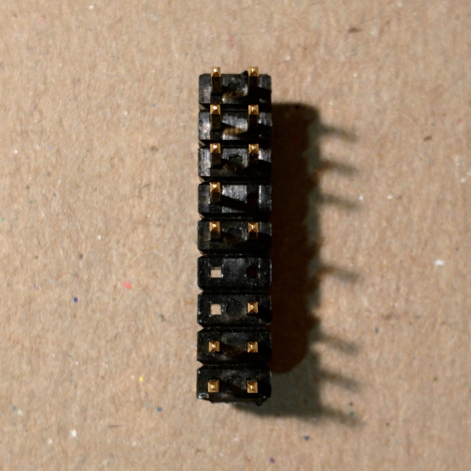
![]() Another common staple of desktop computing is the "AC'97"/"HD Audio" header & breakout modules. Many modern single-board computers feature analog & digital audio, but are often broken out via consumer audio jacks. These small computers could leverage the AC'97 header with great ease -- reducing circuit-board complexity & increasing design flexibility. A source of confusion for many, however, is S/PDIF headers on motherboards. Legacy graphics cards often shipped with a tiny cable for routing digital audio. S/PDIF headers are not well standardized & may consist of two to eight pins. Given this problem, I opted to append five pins to the end of the "AC'97"/"HD Audio" header. This keeps compatibility with off-the-shelf desktop audio modules yet allows S/PDIF in/out on a custom header if so desired.
Another common staple of desktop computing is the "AC'97"/"HD Audio" header & breakout modules. Many modern single-board computers feature analog & digital audio, but are often broken out via consumer audio jacks. These small computers could leverage the AC'97 header with great ease -- reducing circuit-board complexity & increasing design flexibility. A source of confusion for many, however, is S/PDIF headers on motherboards. Legacy graphics cards often shipped with a tiny cable for routing digital audio. S/PDIF headers are not well standardized & may consist of two to eight pins. Given this problem, I opted to append five pins to the end of the "AC'97"/"HD Audio" header. This keeps compatibility with off-the-shelf desktop audio modules yet allows S/PDIF in/out on a custom header if so desired.
Pro audio is also an important area to focus on.Since part of this spec features analog audio next to other digital signals, there is a greater risk of noise. Many environments do not require pristine audio conditions. Some do. This is why I have included support -- in certain connectors -- for AES Digital Audio. S/PDIF is the consumer version of AES. AES42 has some really great features that quite a few sound engineers enjoy. These signals are generally sent on a standard 3-pin XLR connector. There is risk, though, in sending digital signals on a connector primarily used for analog audio. Audio mixers may get damaged if a AES signal is connected to an analog input. I have proposed a spec for 6-pin IEC XLR connectors to hopefully address this issue -- and add a feature or two. The 3-pin connector only allows for one-way transmission of digital audio signals (generally). A 6-pin connector allows for power & bi-directional AES transmission. This opens up doors for chainable digital effects processors, digital audio pedals, mics & remote monitoring. For instance, an artist performing on stage generally needs a mic, guitar input & monitor mix. This could be accomplished via this single XLR cable. The monitor mix would arrive on the `digital-audio-aes-host-out-client-in` pins, and the audio source(s) on-stage would be sent back to the mixer via the `digital-audio-aes-client-out-host-in` pins. These on-stage modules could be powered via the `fourty-eight-volts-max` pin.
This latest work can be seen on the incoming branch of retrospec.cc. -
The Last Major Revision
08/17/2015 at 05:35 • 0 commentsMaker Faire Bay Area 2015 and the events leading up to it really helped refine the specification in a few very important ways. First, I found many of the features packed into the DB-25 spec should be moved to DA-15. This was in an effort to make the spec more accessible as one gets started. The DA-15 spec is not the best candidate for a plethora of chained modules. If chainability is your main focus, shift over to DB-25 and/or DE-9.
The old version of the spec featured USB and lacked CAN. USB is difficult to support when chaining is considered. USB is also a riskier thing to mess around with, since it probably has an expensive computer connected to it. CAN, on the other hand, chains easily and can be run over long distances. It is not as fast, but is sufficient for many electronics experiments. It is used extensively in automotive, automation & robotics environments.
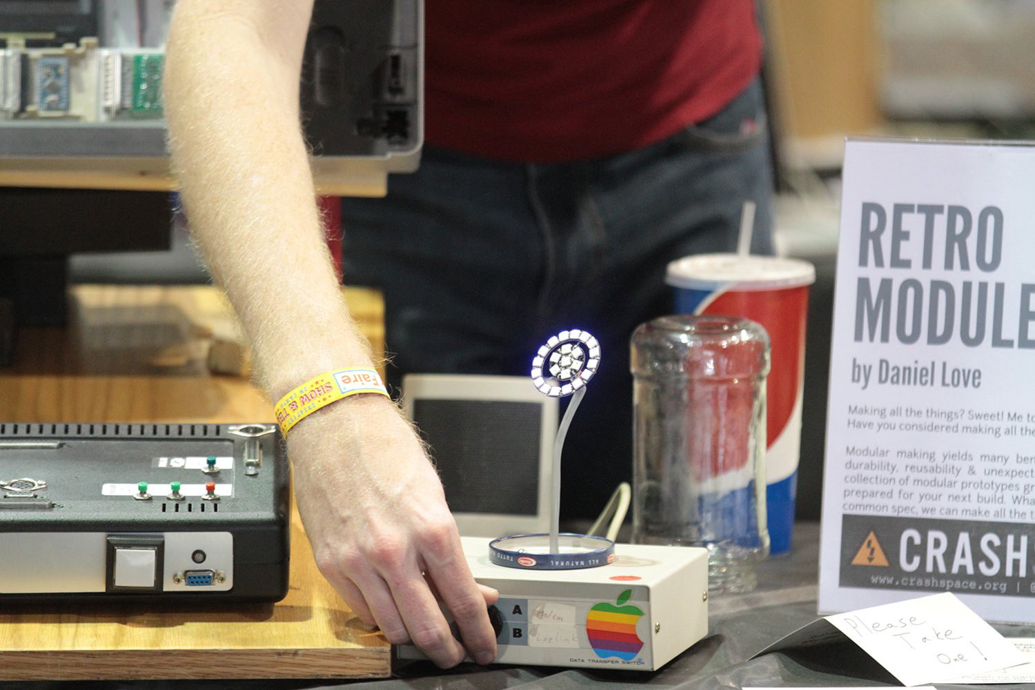
Finally, after taking a look at some other multi-pin connectors, I found it wouldn't be to difficult to support 1080i HD video. While not the cleanest means of transmitting video, it is an ideal transmission method for those who like to tinker. The other connectors I mentiond combined composite, 'super' video & component video onto three pins. This pattern has been followed with the DB-25 connector pin spec.![]() When I decided to make an appearance at Maker Faire, I knew I would need a set of modules to help attract interest. I chose to embed a number of modules into an old flatbed scanner -- along with an Arduino Uno to run everything. The control surface featured all sorts of buttons & fiber-optic-backlit DE-9 & DB-25 connectors. The buttons & LEDs were driven by I2C port expanders & the NeoPixels via the `pixel-bus`. When one (or a few) of the buttons were pressed, the pin holes corresponding to the button label(s) would illuminate. Since I already had a 16x8 I2C LED display, I programmed the Arduino to display button label text there as well. The LED display was behind the scanner glass, while the control surface was mounted on a board well below. The scanner 'display case' and other parts of the display were linked by a single 25 connector ribbon cable. There were other means of input & output as well. Important to the design: I needed certain modules to protected, while others could be messed with. Those goals were well achieved.
When I decided to make an appearance at Maker Faire, I knew I would need a set of modules to help attract interest. I chose to embed a number of modules into an old flatbed scanner -- along with an Arduino Uno to run everything. The control surface featured all sorts of buttons & fiber-optic-backlit DE-9 & DB-25 connectors. The buttons & LEDs were driven by I2C port expanders & the NeoPixels via the `pixel-bus`. When one (or a few) of the buttons were pressed, the pin holes corresponding to the button label(s) would illuminate. Since I already had a 16x8 I2C LED display, I programmed the Arduino to display button label text there as well. The LED display was behind the scanner glass, while the control surface was mounted on a board well below. The scanner 'display case' and other parts of the display were linked by a single 25 connector ribbon cable. There were other means of input & output as well. Important to the design: I needed certain modules to protected, while others could be messed with. Those goals were well achieved.![]()
-
Retro Module Introduction
08/17/2015 at 02:09 • 0 commentsHere are a number of the Retro Modules I've been working on as I've been fleshing out the spec. This video demonstrates some of the possibilities provided via this framework. In building the modules, I discovered pros & cons of varying connector specifications. As things became more stable, I found I was able to deploy quite a few modules around the house, shop & truck. Just the beginning...
-
Visited Maker Fair, Got Tips, Submitted Pull Request
06/23/2015 at 07:57 • 0 commentsHey! So I've been working to make a few revisions to the existing specification (http://retrospec.cc), while adding a few connectors to the fray. I aim to make as few revisions to the spec as possible. People should be able to expect a rigid specification as they build. These revisions are directly related to feedback from fellow engineers.
I realized one thing in particular: there needed to be a connector geared toward those first trying out the spec. I decided on the DA-15 connector, since it is familiar yet slightly rare. The more 'pro' pins, in the new proposal, are found on DE-9 & DB-25.
Others communicated their desire for a longer-distance communication protocol present on these connectors. While generic RS-232, RS-422 & RS-485 were in the running, I decided on CAN bus. The bus will ideally provide the communication backbone for each group of modules. Consider CAN for both flexibility & long cable runs, and SPI/I2C for the simplicity & shorter cable runs.
There was another suggestion related to higher-current applications (i.e. motor controllers). There are connectors in the DB-25 form factor that feature a few large pins. These connectors are usually available via an online order and a slow boat. The connectors are a variant of older connectors which featured one or more coaxial connectors amongst the D-Sub pins.
Retro Modules
A free & open framework to help speed along the discovery, design, implementation & testing processes for Makers of all skill levels.
 Another common staple of desktop computing is the "AC'97"/"HD Audio" header & breakout modules. Many modern single-board computers feature analog & digital audio, but are often broken out via consumer audio jacks. These small computers could leverage the AC'97 header with great ease -- reducing circuit-board complexity & increasing design flexibility. A source of confusion for many, however, is S/PDIF headers on motherboards. Legacy graphics cards often shipped with a tiny cable for routing digital audio. S/PDIF headers are not well standardized & may consist of two to eight pins. Given this problem, I
 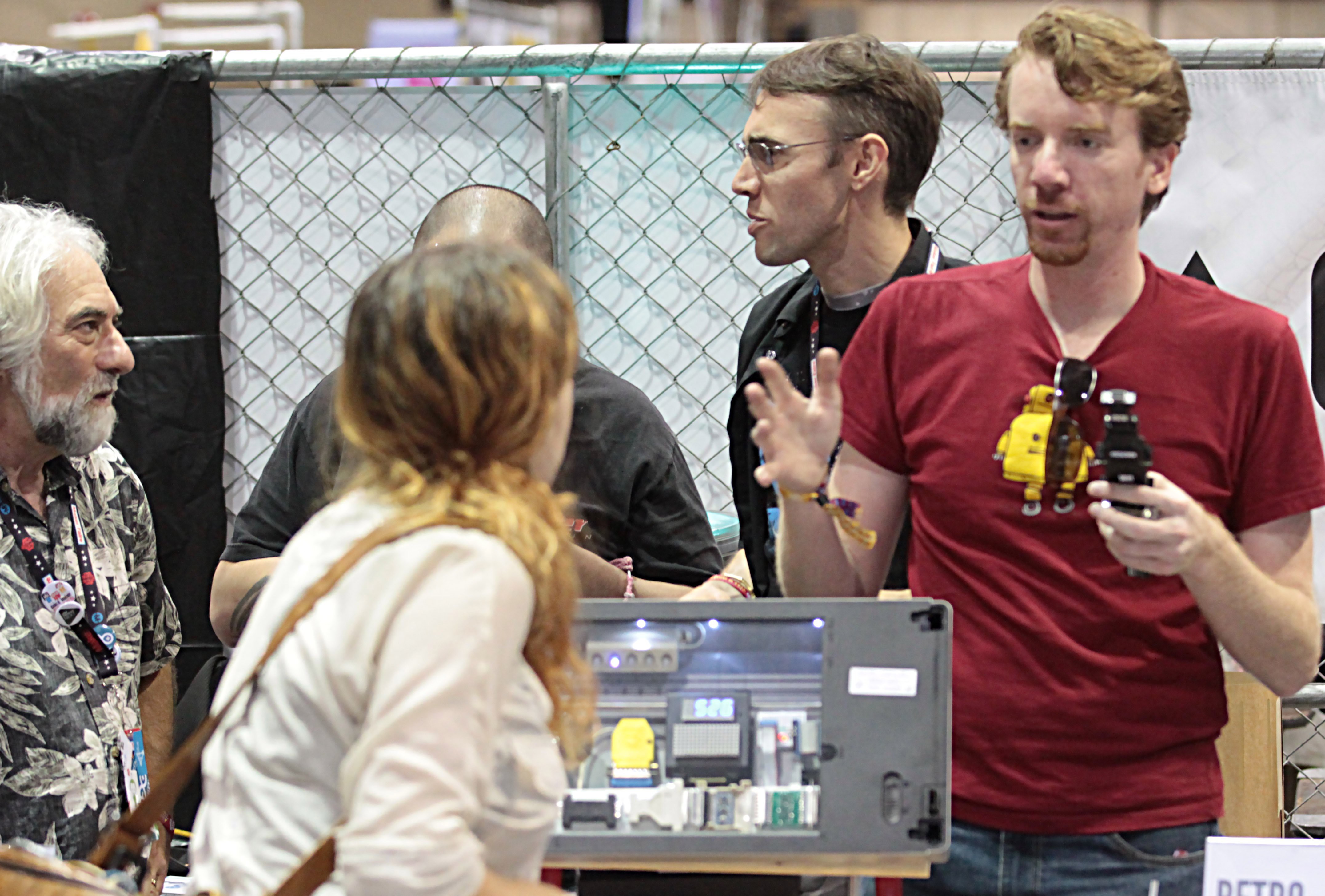 When I decided to make an appearance at Maker Faire, I knew I would need a set of modules to help attract interest. I chose to embed a number of modules into an old flatbed scanner -- along with an Arduino Uno to run everything. The control surface featured all sorts of buttons & fiber-optic-backlit DE-9 & DB-25 connectors. The buttons & LEDs were driven by I2C port expanders & the NeoPixels via the `pixel-bus`. When one (or a few) of the buttons were pressed, the pin holes corresponding to the button label(s) would illuminate. Since I already had a 16x8 I2C LED display, I programmed the Arduino to display button label text there as well. The LED display was behind the scanner glass, while the control surface was mounted on a board well below. The scanner 'display case' and other parts of the display were linked by a single 25 connector ribbon cable. There were other means of input & output as well. Important to the design: I needed certain modules to protected, while others could be messed with. Those goals were well achieved.