 Jon Davies "Woody"
I noticed that the supplied break-out boards ['Tube Cells'] were missing a couple of holes for leads that exist on the IN-14 tubes. This initially had me thinking that I'd been sent the wrong parts by mistake, but the Silk Screen definitely said 'IN-14', so once again I started digging around the PV Electronics site for information about soldering the IN-14 tubes to these 'tube cells'. The answer came in the form of the Nixie QTC Assembly Instructions [p21].
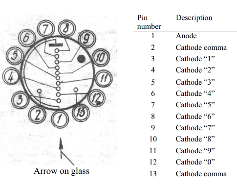
The instructions tell you to clip off the two leads either side of the Anode, which got me to thinking what those two leads were for. After a bit of hunting on an Image Search, I found a pinout diagram that shows the pins as 'comma' aka 'decimal'. The tube cells don't accommodate for these (there are no connections to the pin headers), and I assume that this is done for all tubes used in this 'tube cell' standard.
I'm probably going to drill holes in the 'tube cell' PCBs so I can have the option to re-solder the tubes into a break-out board that supports the commas in future.
Discussions
Become a Hackaday.io Member
Create an account to leave a comment. Already have an account? Log In.