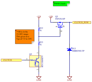
In certain designs we want to use a clutch to hold joints still with a minimal amount of power. The power required to engage an electro-magnetic clutch is higher than the power required to keep it locked. We are using a MOSFET switch with PWM to control the average voltage applied to the clutch. What power rating do we need for this MOSFET?
Side note: why use a high-side P-MOSFET? The use of a high-side switch is preferred because it is typical to link the metal chassis of prostheses to ground and some clutches have their casing grounded. Using a high-side switch can simplify the electromechanical integration. The power requirements being low, it is possible to use a P-Channel MOSFET as a switch (N-MOSFET have better specs and are always used for high power applications, such as the motor bridge). D13 is used as a free-wheeling diode for inductive loads, as a protection for Q3.

P-MOSFET power dissipation:
The clutched used in the experimental setup is rated for 24V 250mA 6W. The unit in hand was tested at 242mA. To accommodate bigger clutches (and other output devices) the calculations will be done for 24V 10W (417mA), used at 10V. The current at 10V will be 174mA.
Using an FDN5618P P-MOSFET:

Where:
ILOAD: 174mA
VOUT/VIN = D = 10V/24V = 0.42
RDS(ON) = 0.315 Ω (worst case)
CRSS: 19pF
VIN: 24V
fSW: 20kHz
Igate: 10.9mA
We obtain & . The total power dissipation is 7.5mW. If the clutch is powered at 24V 10W (no switching) the dissipation will be 55mW. The thermal resistance of the SuperSOT-3 package, from junction to ambient, is 270°C/W.

49C is way below the maximum junction temperature, we do not need to worry about thermal constraints and we can use the FDN5618P P-MOSFET for this application. I used a clutch as an example, but keep in mind that the math is the same for other output devices.
Note: Formulas based on http://electronicdesign.com/boards/calculate-dissipation-mosfets-high-power-supplies
 Jean-François Duval
Discussions
Become a Hackaday.io Member
Create an account to leave a comment. Already have an account? Log In.