 Jean-François Duval
As a starting point, I highly recommend reading AN857 Brushless DC Motor Control Made Easy & AN885 Brushless DC (BLDC) Motor Fundamentals from Microchip. The So, Which PWM Technique is Best? series from TI will then complement your knowledge of BLDC commutation.
===
A four quadrant PWM commutation table is required to support bidirectional motor control with regenerative currents. Figure 66 is part of “So, Which PWM Technique is Best?” by Texas Instrument.
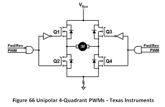
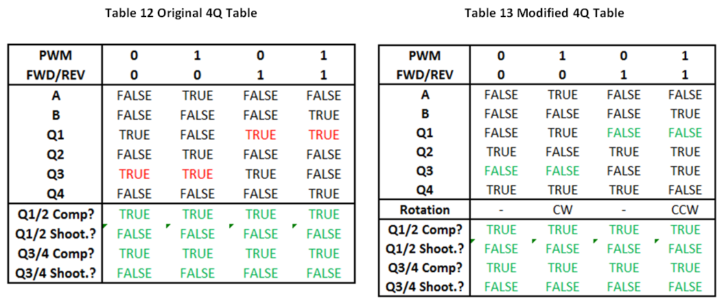
Table 12 was created from Figure 66. ‘A’ and ‘B’ are the intermediary signals, at the output of the AND gates. The red text indicate a problem: this table sets steady-state high values on the high-side MOSFETs. The gate drivers used on FlexSEA-Execute can’t support this. The two NOT gates were moved from the high-side to the low-side to fix this problem, as presented in Table 13. A test was made to confirm that the half-bridges are using complementary switching and that they are never ON at the same time (shoot-through).
This table has to be expanded for three phase brushless motors. The order of the phases is determined by the Hall Effect sensors present in most research-grade brushless motors, such as the Maxon EC-30 used in this experiment. The PSoC 5LP look-up table (LUT) component supports a maximum of 5 inputs and 8 outputs. The 3 Hall sensors and the 2 PWM phases use all the inputs; the Direction signal (to change from clockwise to counter-clockwise rotation) cannot be integrated in the table. Table 14 shows the relation between the input signals and the output signals. MUX0 and MUX1 are used for the analog multiplexer that controls the current sampling.
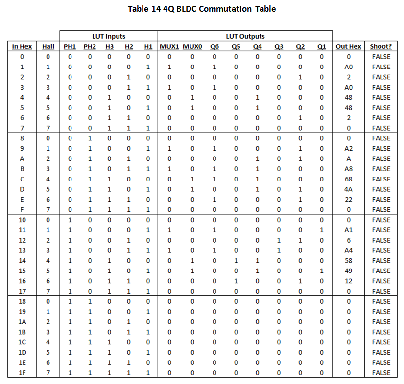
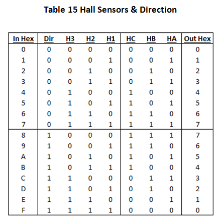
Table 15 presents a second LUT, used to control the direction of the rotation.
Of course, no one likes big look-up table in PNG format, so here’s the Excel sheet I used. The complete system can be seen in Figure 67.

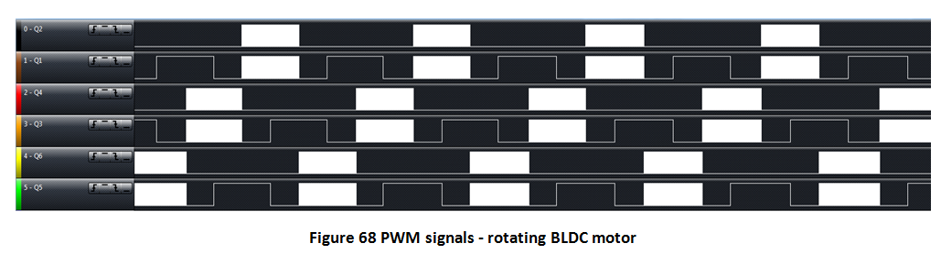
The look-up table is registered with the PWM edge to avoid transitions from happening in the middle of a PWM cycle, when the Hall code is changed; in such an event the dead-time would not apply. The 6 PWM outputs were connected to a logic analyzer while the motor was spinning to confirm the validity of the table:
In terms of code, here's the function that gets called by all the other motor control functions:
//Controls motor PWM duty cycle
//Sign of 'pwm_duty' determines rotation direction
void motor_open_speed_1(int16 pwm_duty)
{
	int16 pdc = 0;

	//Clip PWM to valid range
	if(pwm_duty >= MAX_PWM)
		pdc = MAX_PWM;
	else if(pwm_duty <= MIN_PWM)
		pdc = MIN_PWM;
	else
		pdc = pwm_duty;

	//Save value to structure:
	ctrl.pwm = pdc;

	//Change direction according to sign
	if(pdc < 0)
	{
		pdc = -pdc;	//Make it positive
		MotorDirection_Write(0);
	}
	else
	{
		MotorDirection_Write(1);
	}

	//Write duty cycle to PWM module
	pdc = PWM1DC(pdc);
	PWM_1_WriteCompare1(pdc);
	PWM_1_WriteCompare2(PWM2DC(pdc));	//Can't be 0 or the ADC won't trigger
}
And here's an extract of the .h file://PWM limits
#define MAX_PWM 760 //760 is 96% of 800
#define MIN_PWM -MAX_PWM
#define DEADTIME 55 //Make sure that it matched the hardwar e setting!
#define PWM1DC(pwm1) MAX(pwm1, DEADTIME)
#define PWM2DC(pwm1) MAX(((pwm1 - DEADTIME)>>1), 10)And that’s it! You now have a complete reference for
sensored brushless DC (BLDC) commutation on a PSoC 5, with a 4Q table.
Discussions
Become a Hackaday.io Member
Create an account to leave a comment. Already have an account? Log In.