Close
0%
0%

Tiny robot family

A family of tiny robots, each with their own way of life.

Similar projects worth following
This is my growing family of tiny robots based on ATtiny controllers, pager motors and photo-transistors.

These three little autonomous vehicles have a lot of similarities such as controller, battery and movement mechanism, and they all percieve the world through photo-transistor eyes. But they are all distinct designs with different capabilities and behaviors. They are the first members of a growing family of miniature robots that I have been playing with off and on for a long time
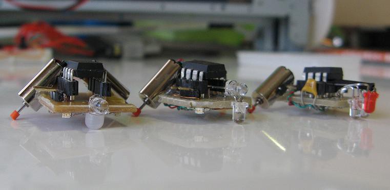

A key aspect of their design is at least one photo-transistor eye and one controlled LED. This allows them to interact in a meaningful way. Depending on how they are programmed, this could be as complex as data transmission between bots or as simple as interfering with the sight of other bots. The resulting interaction would also depend on the type of bots. For example, the eyes of robot 1 point downward to scan the surface, while robot 3 only looks forward.

At this point I have not programmed them for any complex interaction. Their main behavioral features are thus:

  • Robot 1 - Has left and right eyes looking down. Can detect lightness patterns on the ground. Here is a video of it acting as a line follower.
  • Robot 2 - Has one downward eye and one forward. Controlls a group of LEDs around its perimiter. It can see the lightness of the ground and look forward. It can also signal in all directions with the LEDs.
  • Robot 3 - Has one eye looking forward and two separately controlled LEDs pointing about 45 degrees to either side. It is supposed to be able to detect obstacles and determine which direction to turn to avoid them. I am still developing this feature.


The hardware:
The controller could be any of the 8-pin ATtinys. I have used the tiny85 because that's what I had on hand. I have considered a version based on the ATtiny10, but haven't gotten around to that. The batteries are LIR2032 rechargeable lithium coin cells that I pulled out of some solar key chain lights from the 100yen shop(dollar store). They don't last very long between charges, but I'm not planning on spending much money for fancy new batteries.
Here is the underside of each one.


You can see the 2N7002K mosfet transistors for driving the motors. There are also various resistors, capacitors and LEDs. The schematics are here:
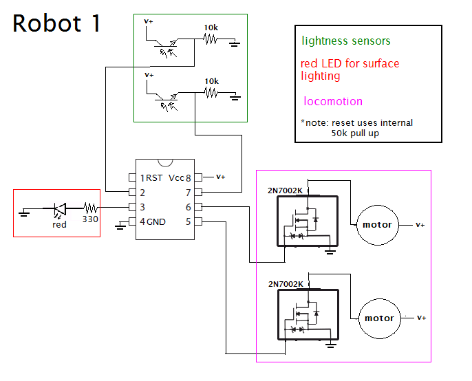
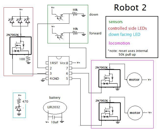
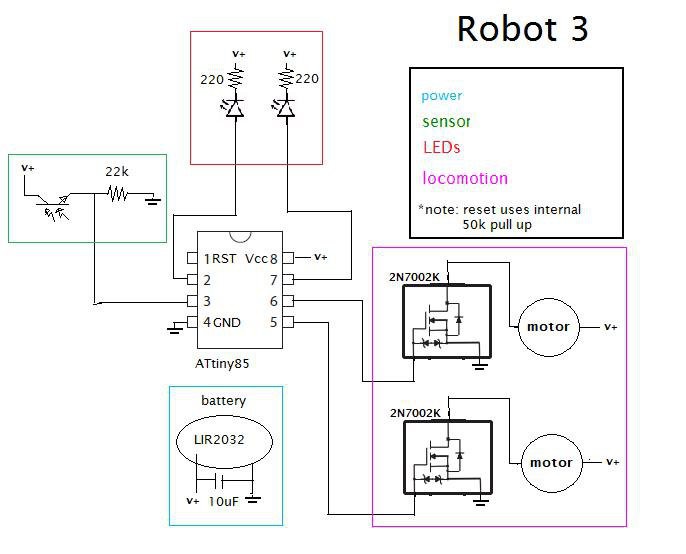
The software:
At this point, the software is very simple, but it is easy to add another behavioral pattern in the code since the main loop simply calls a behavior function. Robot 1 has a line following bahavior. Robot 2 scans the ground and can signal to other robots in the area. Robot 3 avoids obstacles(still working on that one). I would be willing to upload the current code if requested, but since it is continually changing and far from complete, I won't put it here just yet.

If I make new robots, videos, changes etc. I will post a log here about it.

  • 1 × ATtiny85 Microprocessors, Microcontrollers, DSPs / ARM, RISC-Based Microcontrollers
  • 2 × 2N7002K MOSFET Discrete Semiconductors / Transistors, MOSFETs, FETs, IGBTs
  • 2 × small motors from andromedabots
  • 1 × some red LEDs
  • 1 × some ASDL-6620 phototransistors

View all 7 components

View all 2 project logs

Enjoy this project?

Share

Discussions

Crypto [Neo] wrote 05/06/2015 at 17:36 point

These are the cutest little things ever! I really like them, are you going to be having PCBs made for them? You might want to consider Elecrow, with their PCB service I'd imagine you could get PCBs for less than $.7 USD. Nice project! Check mine out if you get the chance :D

  Are you sure? yes | no

pepeu wrote 04/26/2015 at 09:33 point

Hey! Very interesting project! Do you know of a replacement for the ASDL-6620 since they seem to be out of production/stock? 

  Are you sure? yes | no

shlonkin wrote 04/26/2015 at 12:19 point

There are many different phototransistors available. Just look for one that works with visible light and fits your voltage needs. I don't have time now to search for a replacement, but your supplier should have some kind of phototransistor that should work.

  Are you sure? yes | no

Lumor wrote 03/28/2015 at 22:45 point

Hey awesome project, i'm gonna try this myself sometime. Is there a reason why you don't have a power switch so you don't have to disconnect the battery everytime? A small dip-switch wouldn't need much extra space.

  Are you sure? yes | no

shlonkin wrote 03/29/2015 at 00:20 point

Hi. Just for simplicity and because I didn't have any really small switches.

  Are you sure? yes | no

vsureshkeerthi wrote 03/11/2015 at 14:19 point

what is the specification of the motor used in this??? 

  Are you sure? yes | no

kumkum1kiran wrote 02/23/2015 at 10:23 point

Hii.... gud work...

Do you Know...It's very funny and an interesting job to build an Art Robot that can do art or drawing with you…a Robot Art!!! Want more information...just check out...

https://www.mepits.com/project/265/Science-Projects/How-to-make-a-Robot-Art,-A-simple-DIY-Art-Robot-!!!

  Are you sure? yes | no

Sandeep Kumar Singh wrote 02/15/2015 at 22:06 point

I want to build it..It cool but when i go through your procedure then i found some codes i just  want to know how to upload it in IC  with arduino... please help me out 

  Are you sure? yes | no

Sandeep Kumar Singh wrote 02/15/2015 at 22:11 point

I join this site today so no idea.. plz

  Are you sure? yes | no

Adam Fabio wrote 02/16/2015 at 06:27 point

Sandeep, the tiny robots run on ATtiny85 processors. Do you have an ISP interface? (That's the easiest way to program them)

  Are you sure? yes | no

Sandeep Kumar Singh wrote 02/17/2015 at 05:13 point

No, In fact i don't know about ISP Interface... Can you tell me how t make.buy it... 

  Are you sure? yes | no

rellik1000 wrote 02/08/2015 at 14:55 point

Love the project.Trying to breadboard #1 before building it,without success
I'm really just a noob,but shouldn't line 34 .ino #define rsensepin 1 //ADC1 pin 7
be...#define rsensepin 2 //ADC1 pin 7

My apologies if i am missing something.

I am using leds in place of motors for testing.I should see a change in leds brightness based on sensor values....correct?

  Are you sure? yes | no

shlonkin wrote 02/09/2015 at 11:36 point

Due to the vary awkward way the ATtiny85 libraries work, if you call analogRead(1), you will get the value from ADC1(pin 7), but any digital function with 1 will use PB1(pin6). So the definition really should be 1 because only analogRead() is ever called.

If you are testing with LEDs, you will only see on or off. The program does not actually change the pwm value.

  Are you sure? yes | no

Coye Knoll wrote 12/30/2014 at 11:26 point

radioshacks zip zaps those tiny remote control carsuse the same types of motors. u can buy like just the motors,

  Are you sure? yes | no

Mr. Spriggs wrote 12/28/2014 at 04:29 point

Hey,

I dug through the data sheet and came up with a low power version. It works just the same as you original but the ATtiny uses less than half the power the original used.

  Are you sure? yes | no

shlonkin wrote 12/28/2014 at 05:38 point

Cool. Are you shutting down parts of the controller between sensor readings? I'm sure the vast majority of the power is consumed by the motors, so the benefit may be small in the end. But don't let that discourage you from tinkering with it!

  Are you sure? yes | no

Mr. Spriggs wrote 12/22/2014 at 07:23 point
Shlonkin,
So after a whole bunch of testing I finally got the tiny robot working. It was so simple I could kick myself. The problem is with the code. The ledon and the ledoff are swapped. When the led should be on like getting sensor data it off.
I replaced the #defines with
#define ledoff PORTB &= ~(1 << 4)
#define ledon PORTB |= (1 << 4)
And now it works great.

  Are you sure? yes | no

Mr. Spriggs wrote 12/19/2014 at 06:32 point
The problem was right there all along I wired the emitter and collector backwards. Thanks for the help.

  Are you sure? yes | no

Mr. Spriggs wrote 12/17/2014 at 20:11 point
Hey Shlonkin,
So I basically built a copy of your first robot. Then dumped the hex onto the 85. I had no luck getting the great results you have on your video. I played with the setting over and over with no luck. Mine seems to see lines that are not there. I even went and added some sleep mode code to minimize the noise when its reading the sensors.
Any insight?

  Are you sure? yes | no

shlonkin wrote 12/18/2014 at 12:50 point
Here is something you could try. Check the sensor voltage directly with a meter while on a white surface then on black. There should be a significant difference in voltage between them, like around half of your battery voltage in difference. This should be true for both sensors. If you have that, then it is likely a software issue. You are running at 8MHz, right? Try the default sensitivity of 3.
If you are not getting sufficient voltage difference, try changing the resistance value in the sensor circuit. It could be too high or too low.

  Are you sure? yes | no

Mr. Spriggs wrote 11/30/2014 at 18:21 point
I built basically a copy of your Robot 1. Im planning on giving it to my nephew as a X-mas. I was wondering are you running it a 8 MHz or 1 Mhz
Thanks

  Are you sure? yes | no

shlonkin wrote 12/01/2014 at 11:43 point
I was running it at 8MHz. It would work fine at 1MHz, but you'd want to change some of the numbers in the code to compensate for the slower clock.

  Are you sure? yes | no

DayDreamingPhd wrote 08/20/2014 at 09:22 point
I'v been looking at an old 1920 valve amp radio & loking to buy 1 to rebuild & stil keep the valves make it into annolg to digital & if I could get a few people helping m,e this would be grate fun , I have no exspeerence in elictronics & programing. but this would make progject to be on www.kickstater.com .

  Are you sure? yes | no

bootdsc wrote 08/14/2014 at 23:09 point
Looks like someone found an old BEAM robotics article and decided to pass it off as there own.

  Are you sure? yes | no

shlonkin wrote 08/15/2014 at 05:23 point
Not really, though they do look kind of similar. I've never seen a BEAM bot with a microcontroller, but then again I've never read a BEAM robotics article.

  Are you sure? yes | no

ZaidPirwani wrote 08/07/2014 at 06:30 point
well, here is what I did yesterday...
https://github.com/Ejaad/tiny85Bots

  Are you sure? yes | no

shlonkin wrote 08/07/2014 at 08:16 point
That's a really cool robot! How well does it work? Do you have a video of it?
I really like your idea of glue stick wheels, but I'm guessing that thing goes way fast.

  Are you sure? yes | no

Eric wrote 07/27/2014 at 14:20 point
Saw this on sparkfun today and immediately thought of the robot family: essential sensor kit https://www.sparkfun.com/products/12862. Needless to say, desired components could be sourced individually more cheaply, but a good example of the possibilities.

  Are you sure? yes | no

Eric wrote 07/23/2014 at 14:07 point
So as a first effort to create a educational development platform for these little guys, I have created a PCB design that incorporates the key components, prototyping area for adding the sensors, and a usb charging circuit to allow charging the coin cell. Note that I am just a hacker, not an electrical engineer, and this is totally unverified/untested. But if interested, please improve/correct/modify! https://github.com/erikor/tinybot

  Are you sure? yes | no

shlonkin wrote 07/24/2014 at 12:33 point
Awesome! If you are going to make these, you should definitely post a project and let me know. I haven't looked over your designs yet, but hey, I'm no expert either. I'm a kindergarten teacher.

  Are you sure? yes | no

Eric wrote 07/25/2014 at 05:59 point
Ok...project residing at http://hackaday.io/project/2054. (These are a bit larger than yours...3.5 x 4.8 cm. The main size limitation is the size of the coin cell. I could not find a smaller coin cell with anywhere near the capacity that wasn't 3 x more expensive, but the hunt continues). First batch of PCBs is ordered and should arrive in 1-2 weeks!

  Are you sure? yes | no

ZaidPirwani wrote 07/16/2014 at 15:36 point
so i have got my motors delivered today - awaiting ATTiny85s now... while I wait,

thinking to over-engineer this:
design a 3d motor/PCB holder and print it with my still experimental 3d printer
design a PCB for the 3d printed PCB holder

OR
just put everything on a vero board with lots of glue and wait till ATTiny85s arrives

  Are you sure? yes | no

Eric wrote 07/16/2014 at 14:18 point
This is really great. So half (most?) the learning/fun is putting this together, but I think it might be neat to have a PCB version that plugs into a usb charger (using the pcb itself as the male usb plug, like this: http://www.instructables.com/id/USB-PCB-Business-Card, and using the quite cheap [60 cents] mcp73831 battery charging chip), an upright battery clip, and has a prototyping area that breaks out the attiny pins to further facilitate adding new sensors.

I am working on just such a design and will share as it progresses. Feel free to comment/give input. Maybe I will put what I have so far up on github in the next day or two.

From a young developer standpoint, my vision is that the PCB could be pre-populated with everything except the sensors...then students could focus on programming, and thinking about what sensors/actuators they want to add. They would still get to solder because they would need to add the sensors/actuators.

Older students could just be given the empty PCB and components, and assemble the whole thing.

By the way, the mcp73831 is only available as a surface mount component. But it seems to me the sooner we get young developers over the fear of soldering surface mount, the better. Plus, this helps keep things small. (I am sure there are other battery charge controllers out there that are through hole). Anyway, the current design makes use of SMT MOSFETs already so that bridge has already been crossed.

  Are you sure? yes | no

Similar Projects

Does this project spark your interest?

Become a member to follow this project and never miss any updates