Small Minimal Heliostat
A heliostat with integrated motors to minimize mechanical complexity, for use in cooking, smelting and energy production.
A heliostat with integrated motors to minimize mechanical complexity, for use in cooking, smelting and energy production.
To make the experience fit your profile, pick a username and tell us what interests you.
We found and based on your interests.

The alignment issues are too much of a headache with the radial stepping design, and the precision is quite poor with that configuration. Inspired by a YouTube video, I've switched directions to pursue a worm drive transmission.

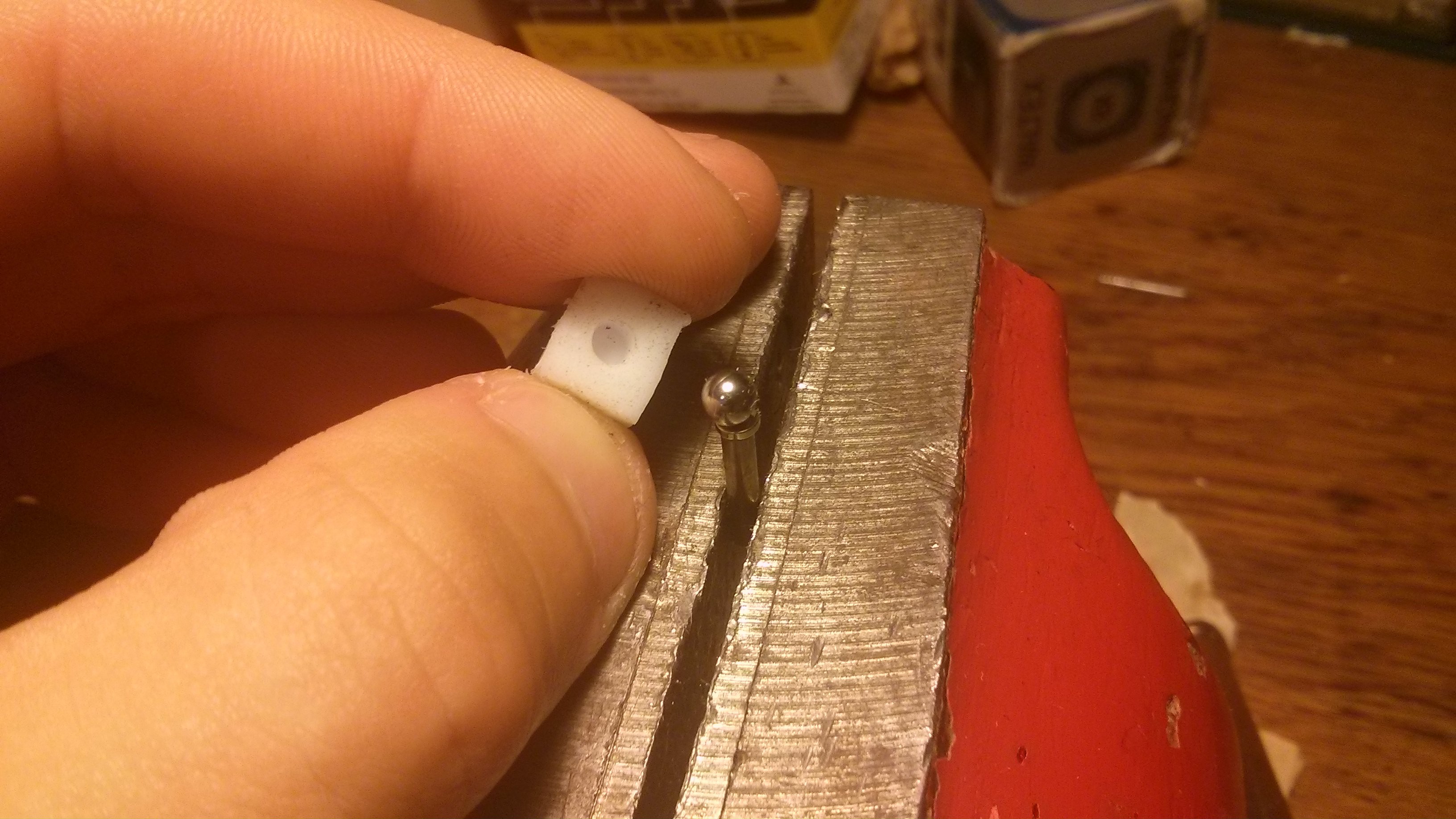
A bearing ball mounted on a shaft, and a piece of hdpe with a drill hole to centre things. There will be an opposing force holding the hdpe (and mirror) down caused by two more bearing surfaces, one on each of the axis rotors.
To prove the concept of integrating the motors into the structure, I need to test that I can actually move a single axis. This video shows that there is enough force generated to move things. As the structure gets heavier I may have to increase the number of turns of wire (and the voltage).
I tried to operate this motor with three coils to allow continuous travel, but I could not align them in such a way as to allow the rotor to hang free without binding. I think that if I can just get the axle of the rotor to be more rigid without drastically increasing the friction, the alignment will be less of an issue.
Access to 3D printed parts would greatly accelerate this project. I would use the printing time to produce the mirror mounting brackets, radial rotors and the fulcrum tower. I would be able to iterate on my initial design right away!
Create an account to leave a comment. Already have an account? Log In.
The mechanical issue is that off-axis rotations are impossible. You can
pitch and you can roll it, but you can't do both at once.
Ah, now I see it. Because the Gimbal is offset from the two axes, a pitch and a roll movement would require some part of the frame to deflect to accommodate.
Thanks Forrest and Philippe for the feedback.
Hi,
I'm not sure but as I can see with this simplified drawing, all this stuff cannot move at all...
Yes, with only one point of contact the initial sketch can't actually work. I've revised my ideas and now have two additional bearing surfaces that keep the rotor structures from binding against the central post as well as keeping the top gimbal from separating.
Is that the issue you noticed?
Have you talked to the folks at VHS?
https://hackaday.io/hackerspace/1027-vancouver-hack-space
They probably have a few 3D printers that you could use..
Become a member to follow this project and never miss any updates
By using our website and services, you expressly agree to the placement of our performance, functionality, and advertising cookies. Learn More
I have a simpler motion control for 3 axis motion if your interested: its 3 ball joints in a triangle, that stands on 3 legs, two of the legs can be extended and retracted via a threaded rod turning in a nut welded to a tube (basic linear actuator) the other is fixed in length. By extending or retracting the legs a relatively short distance a substantial angle can be achieved with fine threads for the extend/retract motion, the position is very solid when at rest. Motion is slow, but suitable for a sun tracker. I'm building a prototype in a couple months, busy with a bigger projects at present, I have some old 3D models somewhere, the first prototype uses two small 24v DC motors with integrated encoders from an ID card printer... I don't check hackaday much, so if you like, feedback to cubespawn at gmail, Cheers!