 AVR
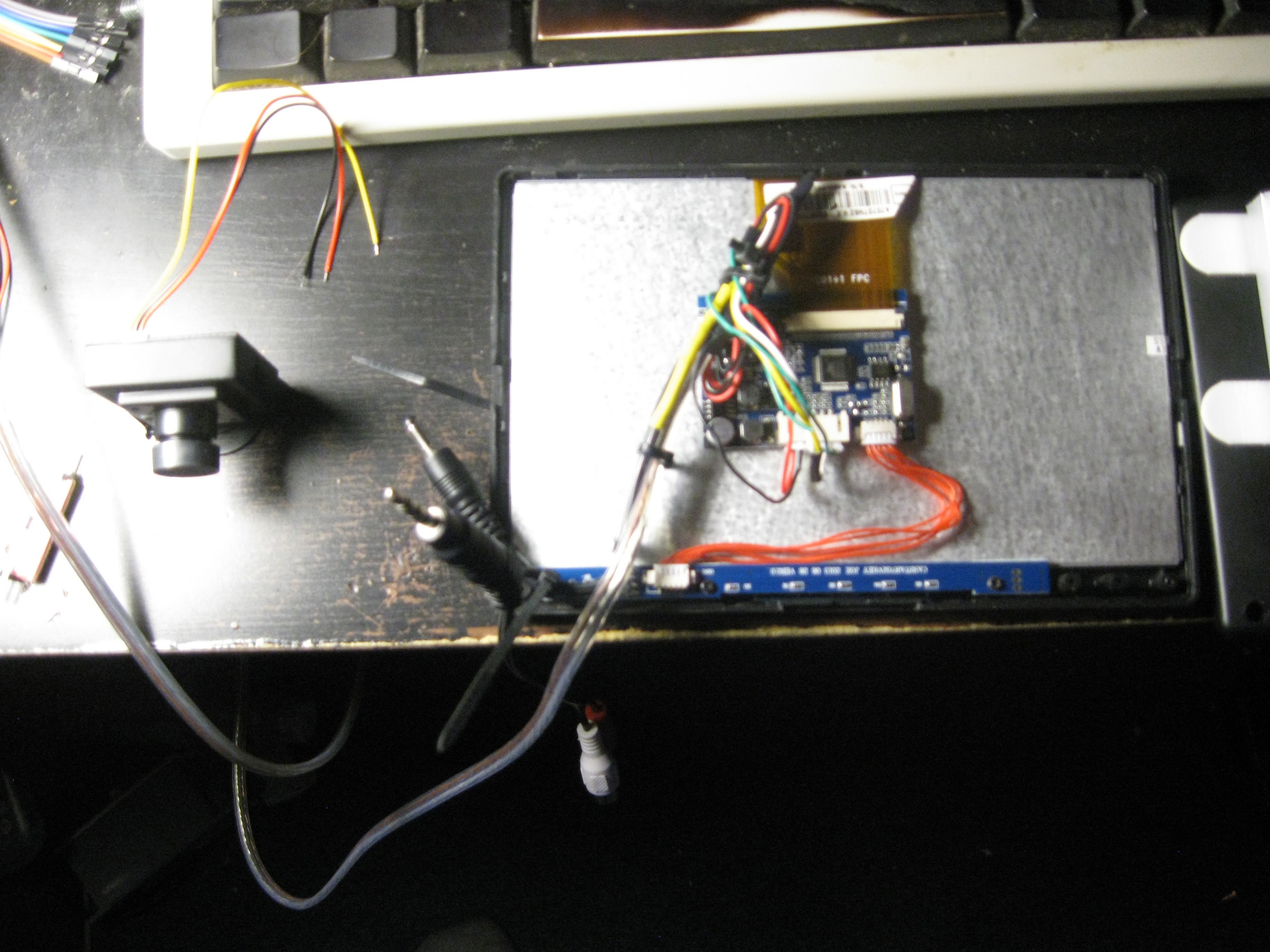
AVRLast week I soldered up and tested my FPV screen. This screen gives me the video feed with telemetry data overlayed from the quadcopter's camera. The transmitter and receiver are the generic PAL 5.8GHZ analog set you can find on ebay or alibaba. This test was merely just a power on test, to test the screen wiring, in a later post I will show the transmitter and camera working.
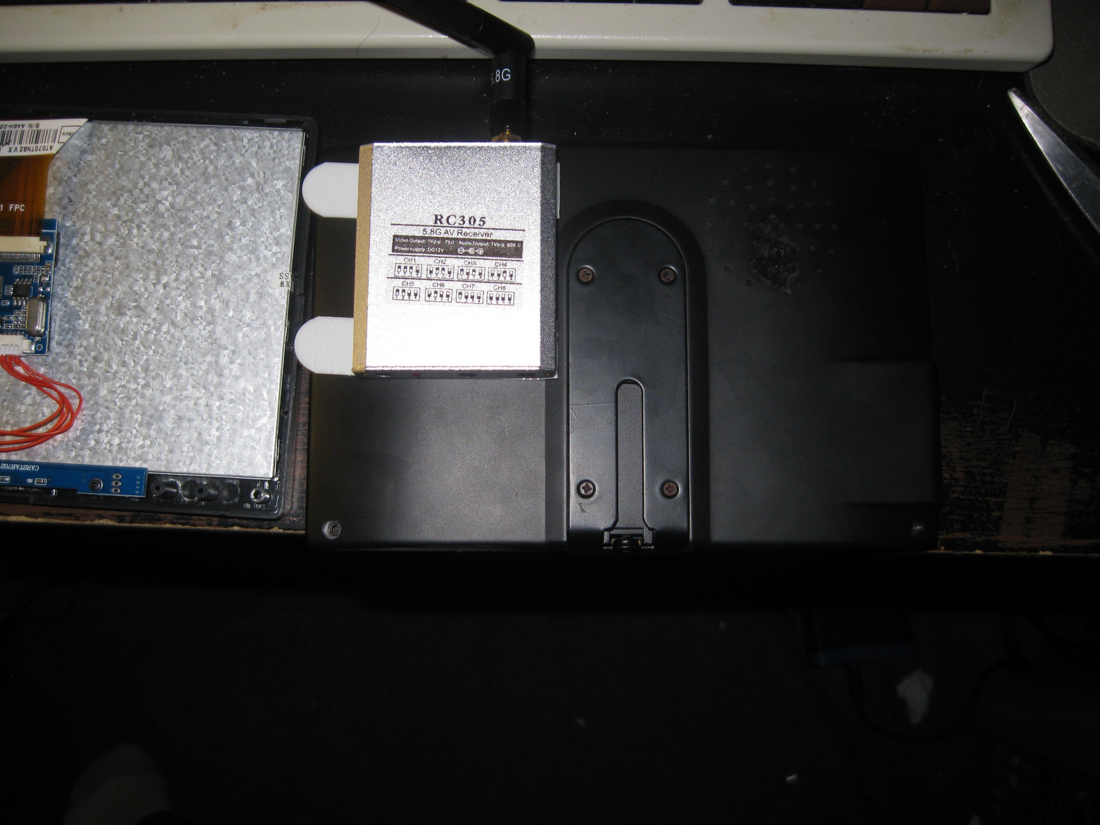
Back cover of the screen, 5.8GHZ PAL receiver attached with command strips, eventually going to make a 3D printed casing to graft to the back of the screen for mounting the PCB of the receiver sans case.
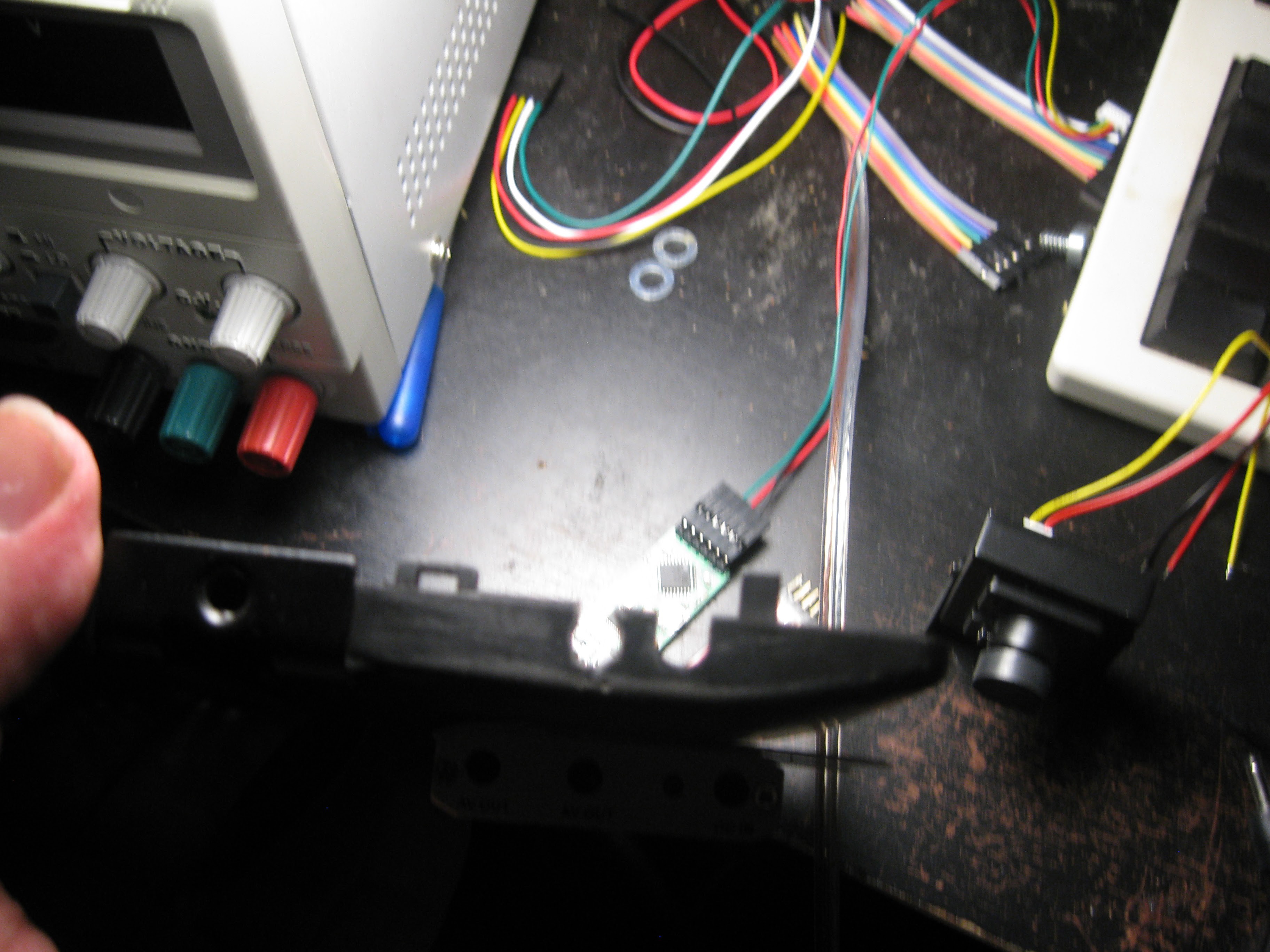
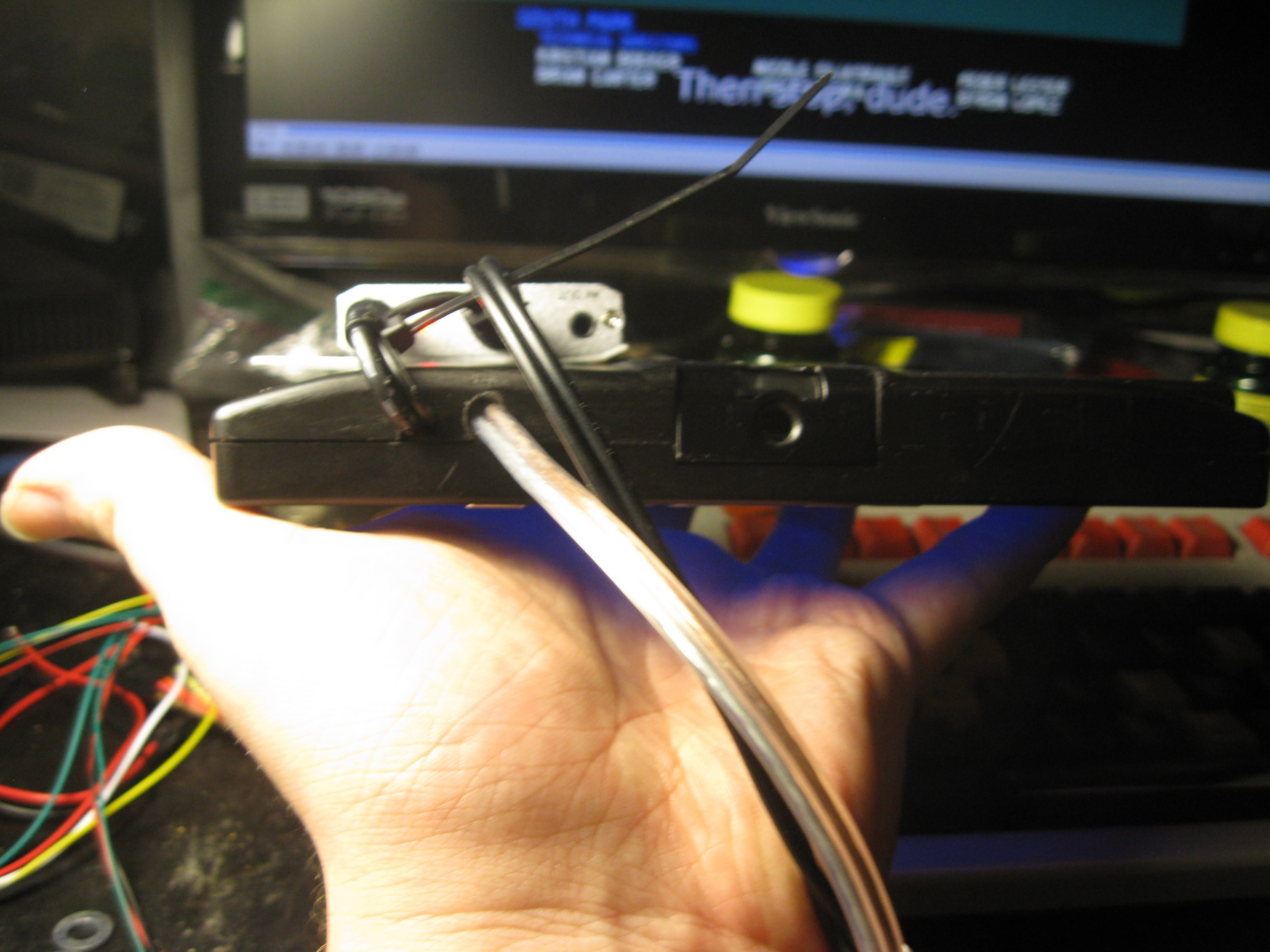
Second hole drilled in place next to stock video cable hole. The second hole is for the power cable that will connect to a battery, the cable is long so the battery can be placed in my back pocket.
All put back together and powered on. Note red LED on 5.8GHZ receiver.
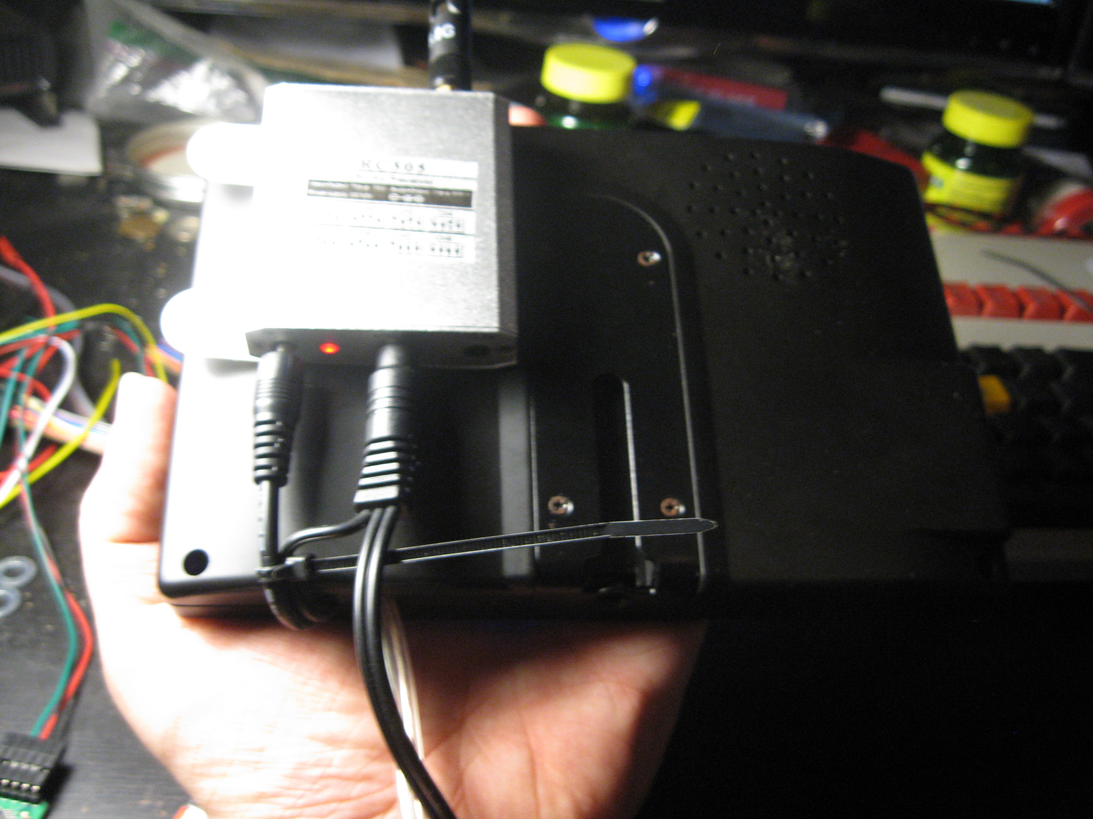
Bottom view, showing wiring from radio receiver into screen, and power cable.
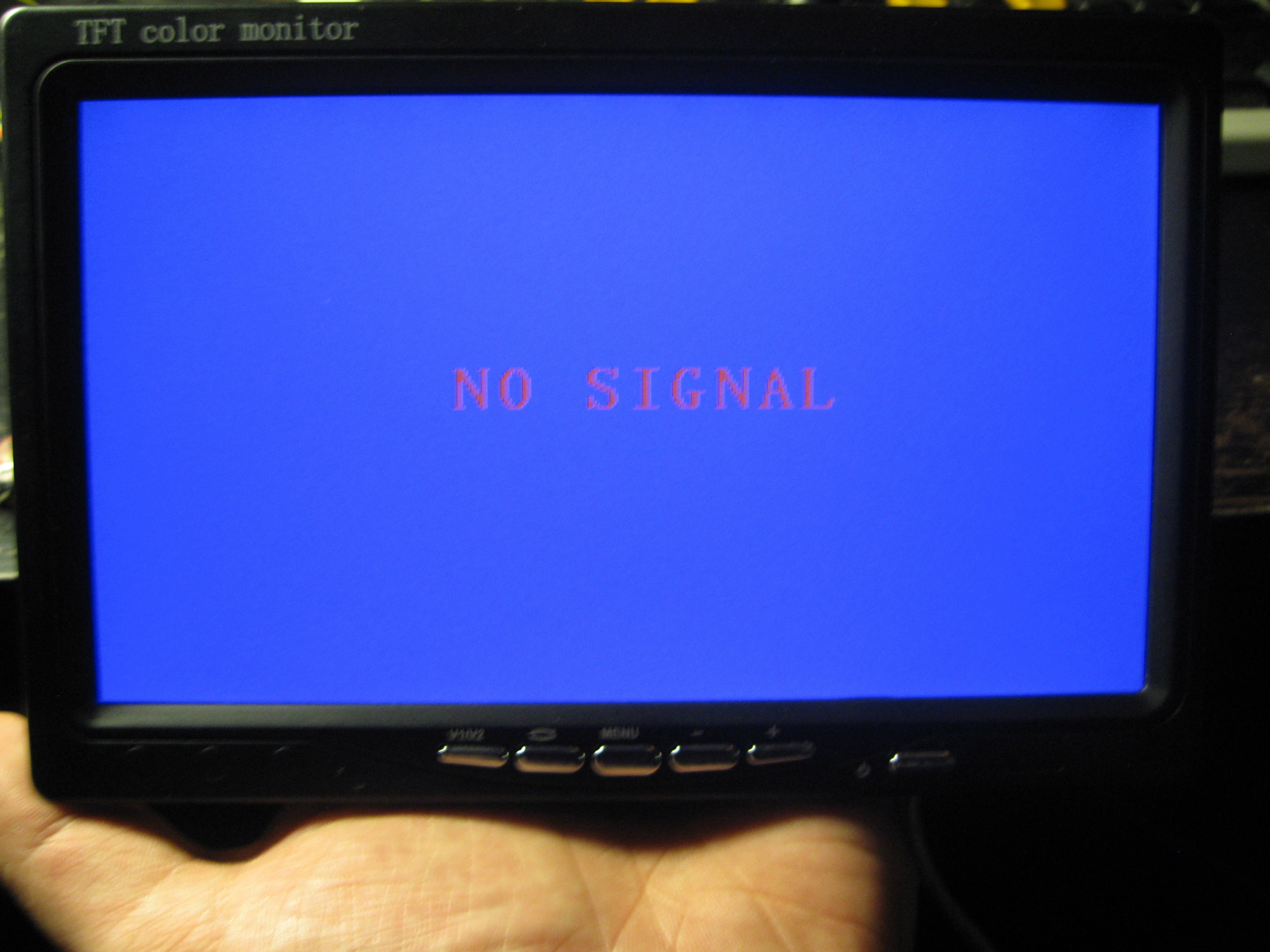
Default screen when no signal is detected on the input. The screen has two analog inputs switchable by the buttons on the front or included remote.
Thats all for the screen test, radio and camera test in next update.
Discussions
Become a Hackaday.io Member
Create an account to leave a comment. Already have an account? Log In.
Is this just a field fpv display, I guess you arent planning on strapping it to your head ;P
Are you sure? yes | no
currently mounting it onto the Turnigy radio I have but I do plan on making a laser cut plywood head mount system ala Oculus rift style. I've seen lots of people do that online lately so I figured why not. But first running it mounted to the controller.
Are you sure? yes | no
Nice, I havent made the jump to fpv yet, but I've been looking at those head mounted kits from hobbyking.
Are you sure? yes | no