 Nick van de Giesen
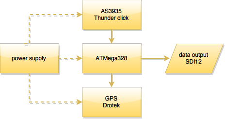
The system consists of four parts:
- Power supply
- AS3935 Thunder click
- ATMega328
- NEA-M8T GPS Drotek
The AS3935 Thunder click and the NEA-M8T GPS Drotek are off-the-shelve PCBs. As these involves RF designs, we decided to go ahead with these solution under the motto “do not solve a problem that has been solved before”. In the final design, we may integrate these PCBs in our own design to save costs. There is an open source design for the AS3935 by Tautic (http://wiki.tautic.com/Category:AS3935_Lightning_Sensor_Dev_Board).
All parts have been tested but the integrated design, hardware and software, not yet. The ATMega328 provides the intelligence to the system but is asleep most of the time. The AS3935 will be in listening mode most of the time, taking 60 muA at 3.3V. Once lightning is detected, an interrupt wakes up the ATMega328, which starts a timer and wakes up the GPS. The data (energy and time stamp) are sent to the TAHMO station through a SDI12 connection.
Power supply
The power supply is relatively straightforward and is based on a design by Jon Viduchic (http://tahmo.org/going-solar-with-tahmo-stations/). We are running a small duration test with the load being a LED and 330 Ohm resistor (15 mW) running on the board. The solar panel is 4cm x 3.5cm.
AS3935 Thunder click
Communication on the new PCB between the ATMega328 and the 'AS3935 Thunder click' has been tested. The led needs to be removed to save energy.
ATMega328
PCB with ATMega has been tested with 'AS3935 Thunder click'.
NEA-M8T GPS Drotek
Communication with GPS has been tested before but not yet putting it to sleep and waking the GPS.
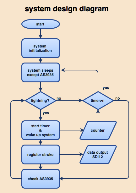
NEXT STEPS
- The software still needs to be integrated according to the flowchart below:
- The SDI12 connectivity needs to be implemented and tested. Code is available at https://github.com/StroudCenter/Arduino-SDI-12/wiki
- A PCB is never perfect so there will be some differences with the next batch. The latest design, and all earlier versions, can be found at the GitHub repository (https://github.com/nvandegiesen/Team_TAHMO/wiki).
- An important PCB improvement is to have a tx/tr connection instead of only the SDI12 connection. This makes on-board debugging and software updates much simpler.
- Housing! We need to make this innocuous, raintight, and affordable.
LICENSES
For the 2015 Hackaday, all licences and permissions have to be documented. In our case, that is relatively simple.
All software is built as open source software under a GNU Lesser General Public License, by others or us. The code is written as Arduino code and all code built by others is recognized as such. We use Codebender as development environment.
The designs are freely available through our GitHub repository (see https://github.com/nvandegiesen/Team_TAHMO/wiki). We used Fritzing for our design.
Discussions
Become a Hackaday.io Member
Create an account to leave a comment. Already have an account? Log In.