Close
0%
0%

AluPi - Pocketable Game and Computer System

AluPi is a portable device designed for playing games and performing general computing which is straightforward to assemble.

Similar projects worth following
The AluPi is an open gaming and computing device based around a Raspberry Pi 2 Model B. The goal of the project is to provide a portable general purpose computing platform that people will want to carry with them. Cell phones are not designed to serve as a general purpose computer. The AluPi aims to solve this issue by providing a full QWERTY keyboard for text entry, a large 5" LCD for more comfortable use, and gaming controls to make the AluPi a device that people will want to carry with them.

The design files are created in free, open-source applications: KiCad, OpenSCAD, and MPLAB X. The AluPi was designed with modularity in mind. Modules such as the keyboard and gaming controls, the battery charging/power system, and the LCD controller can be easily brought into other projects (or even be projects in their own right!)

The AluPi can also power USB devices when unpowered, it can display composite video from external devices, and the input controls can operate over USB.

LCD controller system:

Keyboard/Game control system:

  • Communicates with the raspberry pi (or other device) over USB
  • QWERTY keyboard
  • D-pad, 4+ face buttons, 2 menu buttons
  • Analog nubs
  • Shoulder buttons

Power system:

  • Battery charges over USB while devices are drawing power
  • Power status LEDs
  • Powers the other components (5V boosted)
  • Acts as a portable source of power for other devices

View all 7 components

  • Quick General Update

    Stephen M07/01/2015 at 16:44 1 comment

    Hello Everyone,

    This is a quick update so that you guys are aware of the current status, but I won't go into details.

    The PCBs and all parts came in late last week. I spent the weekend assembling the electronics and debugging/developing code for the microcontrollers. Both had issues connecting to the PicKit, but I resolved both of those. I got the input controller microcontroller communicating with my laptop over USB. There seems to be an issue with both joysticks that I got in one particular axis, and it seems to be a problem with the joystick itself, but it still needs more investigation.

    I screwed up the footprint for the buttons, so I won't be able to fully electrically test them before the next board revision. I can still probe things to make sure things are working properly, so it's not a huge concern.

    I'm still working on the software for controlling the LCD driver, so I haven't been able to test that.

    I also haven't gotten the battery charging circuitry up yet either. During development I find that having a constant source of power isn't what you want while soldering. I probably won't get to it until I am stuck on other things.

    I also just bought a 3D printer! So I'll be able to start working on prototype cases soon. I haven't gotten a shipping notice yet, but I'm hoping to get the printer before the weekend!

    Thanks for reading,

    Stephen

  • Project Cost Summary

    Stephen M06/23/2015 at 03:13 0 comments

    Hello Everyone,

    I've ordered PCBs for the first revision of the circuit board. At this point I have a pretty good estimate for the total cost of the project. I've broken it down at the bottom of this post. The mouser order for this revision of the project can be found here. The battery can be ordered from adafruit, but a larger battery with more capacity and higher discharge rating can be had elsewhere. The adafruit order includes the following (each linked individually): joysticks, LCD, Raspberry Pi 2, replacement USB jacks.

    The costs are as follows (in USD):

    • Mouser order $47.19
    • Adafruit order $78.40 (battery is extra $12.50)
    • Battery $16.68
    • Both microcontrollers pre-programmed $2.94
    • Estimated about $4 for audio circuitry

    In total, the parts come to $149.21 with the better battery before shipping. The PCB price is intentionally not included because the prices vary, and often come in multiples. For this revision I ordered 5 boards for $30 before shipping. That works out to $6 per board. I also left out the cost of 3D printing the case because I don't have any experience with 3D printers.

    With everything added up, I feel like the project is a good value. There is about $115 in big ticket items (RPI, LCD, battery, LCD driver, switches, and joysticks). Most of these items don't have readily available alternate sources, so it would be hard to bring the cost down by trying to replace them. After that there are a bunch of small items like voltage regulators, microcontrollers, other IC's, and passives which begin to add up. At this point I'm fairly pleased with the total, so reducing the cost is something that will go far into the background.

    Thanks for reading! Feel free to comment if you have any questions or anything else you'd like to say.

    -Stephen

  • Big Update - Prototype PCB Design Complete and More

    Stephen M06/17/2015 at 04:48 0 comments

    Hello Everyone,

    I haven't updated recently because I've been focusing my time on working on the project. Normally I update when I hit a roadblock, but in this case I just hit a milestone!

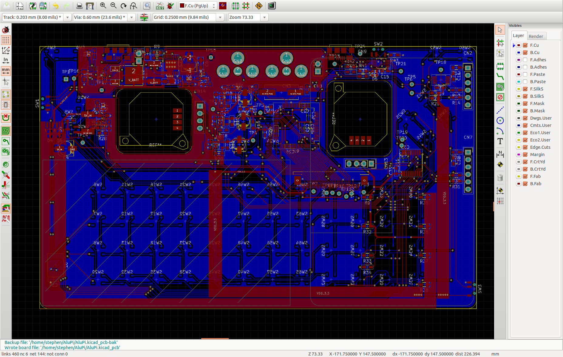
    I finished a preliminary version of the the schematic Friday June 5th. I spent that weekend building up a mouser cart with the parts, and modifying the schematic to better match the availability and cost of components. This took way longer than I anticipated, and resulted in a completely different battery charging circuit, battery, analog nubs, and many other things.

    Initially I was planning on making a prototype circuit board with no mechanical constraints so that I could get a smaller, cheaper board (100mm by 100mm) to verify the electrical functionality. That would mean that I would still need to order another board to do mechanical prototyping, and 3rd board to finalize the project. Instead, I decided to go for the full size board from the start (150mm by 90mm) with mechanical constraints. This made routing very difficult.

    #Start Rant

    The analog nubs, battery, buttons, raspberry pi, and the various connectors caused posed mechanical constraints. No components could be placed on the top side where the battery will sit. No components could be near the push buttons on the bottom of the board. The clearance on the bottom of the board is about 3mm. The analog nubs create huge holes in the middle of the board. The LCD connector had to be in a very specific place so that the LCD cable lines up exactly. The LCD driver had to be oriented a particular way so that the data lines wouldn't cross. Lastly, the raspberry pi USB, HDMI, DSI, CSI, and A/V connectors can interfere with the component placement on the top (and their positions aren't that well defined). And then there are the electrical constraints...

    #End Rant

    There are innumerable things that I could change, but I need to keep moving forward with the project. Major things are: I decided to leave the audio portion of the design to the next board revision, the USB signal integrity will probably be terrible, sub-optimal component placement, and inadequate heat dissipation.

    Things that will be changed for this revision will be changing the top right and top left buttons to right angle tact switches, and moving silkscreen designators.


    Mechanical Stuff

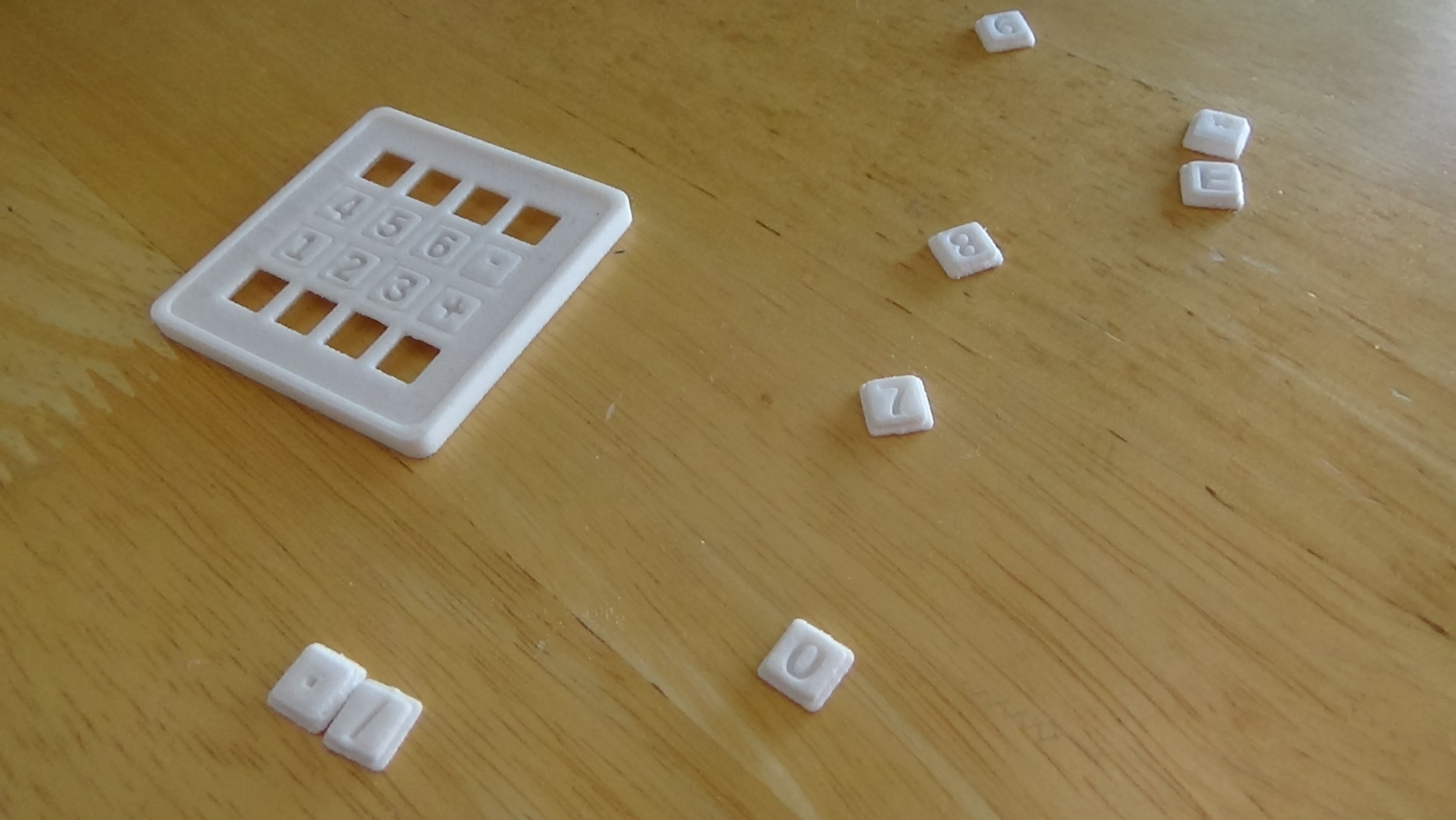
    I got my little keypad thing from shapeways! Unfortunately I didn't start my project early enough to get the free credit, but it was inexpensive enough anyways when there are few other options (like $6 before shipping). I put in small supports between the buttons so that they would be one part during manufacturing. I was able to break them all out, but it was a bit difficult to remove the middle ones (the ones still attached in the picture below). Since I don't have sandpaper I can't do the post-processing that they need. Based on the buttons that came out cleanly, and despite not having a PCB to test with, it seems like the design works fairly well. I want the 3D printed pieces to be manufacturable using a consumer 3D printer, so I might have to buy one to start prototyping with.

    Software

    Since I want the design to be platform agnostic, there will be no custom software on the raspberry pi. To achieve this, the keyboard and gaming controls will interface with the raspberry pi through a microcontroller over USB. I ordered a USB dev board so that I could start working on the microcontroller software (with a known good board) before getting my boards in.

    Things are coming along!

    Thanks for reading,

    -Stephen

  • Mechanical Design Log 1 - OpenSCAD and 3d Hubs Sad

    Stephen M06/03/2015 at 06:36 0 comments

    Hi Everyone,

    I made some progress on the mechanical design of the AluPi this weekend, and I thought I'd give an update.

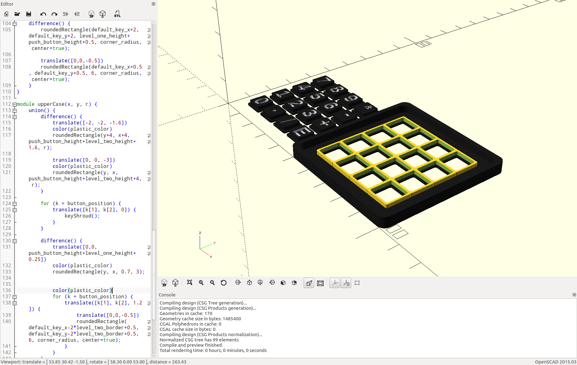
    I'm trying out OpenSCAD for the mechanical design and planning of the device. OpenSCAD allows you to define geometry programmatically. This makes it relatively easy to create parameterized geometry. The case design I'm working on (not shown), and the numpad shown in the image below use basically the same code. I have data to define the position and symbol on each button, general button properties (width, length, symbol padding etc.), and size of the case. Everything else is produced from that information. If you've done programming before you should definitely give it a try. I've mainly used SketchUp for mechanical designs and sketches (as you can see in a previous project log and the project thumbnail), but I wanted to make this project as open as possible. I've even been burned very recently from SketchUp because I migrated to a Windows Vista machine. Since SketchUp doesn't support anymore, I had to venture to the corners of the internet to find an old installer.

    I wanted to get a rough idea of how the mechanical design would work in terms of the buttons, so I sent the model shown above to a person who lived near me through 3d Hubs. Sadly, the print order was declined. I haven't spent the time to look for another "hub" to print the design, but I'll need to try again at some point later on in the project. I don't really need to get anything printed at the moment, I was just hoping to get some early feedback on the mechanical design.

    Thanks for reading!

    -Stephen

  • Display System Design (Mini) Log 2 - Breakthrough

    Stephen M06/03/2015 at 05:52 0 comments

    After many, many hours of searching, I think I've found a single chip solution (almost) for driving the LCD from the composite output of the raspberry pi. The salient features are:

    • About $10 in single quantities
    • NTSC, PAL, SECAM, etc. input
    • "TFT panel support" with "8 bits per pixel" (I really hope this means per color)
    • Supports up to 800x600 LCD panels
    • Configured over I2C
    • In stock at Mouser

    The reason it's almost a single chip solution is that the configuration can be done the microcontroller that handles the keyboard input, but a microcontroller would need to be added to the design if the display system was used in a separate design.

    And before I forget, it's the TW883* series of TFT display controllers. I'm still waiting on the datasheet from intersil (grr...) to make sure it will actually work as I inferred

  • Display System Design Log 1 - Pixels and Chips

    Stephen M05/27/2015 at 05:27 0 comments

    Ideally there would be an IC which takes in a composite video signal (in its many forms) and drives a variety of different LCDs (especially the one I'm planning on using). It seems as though they exist. You can buy LCD driver boards on eBay which take in composite and drive an LCD, and it looks like a single chip solution. The downside is that I haven't been able to find a datasheet, or a reliable source for any of these chips. If I recall correctly, Analog devices also has an IC which takes in composite and drives and LCD. The (major) problem with this is that it is designed as an integrated solution for TV's and is massive (in terms of area and price).

    The best solution seems to be using an IC dedicated to converting the video input into a digital format (search "ntsc decoder ic"), and using an FPGA to drive the LCD from the information received. From what information I've gathered so far, the typical output resolution of the decoders is 720x525 (NTSC) or 720x625 (PAL). This pixel data would need to be scaled to the appropriate size for the display. Storing 3 lines of video data just about fills the block RAM for the FPGA dev board I'm using. This should be just enough of a buffer to scale the pixel data and output to the LCD. It would be a huge pain to have to use external RAM, so I really really hope this works out.

    I've ordered an LCD from Adafruit to play around with. I haven't been able to find a better deal on an LCD screen, so it's in the design for now.

  • Input System Design Log 1 - Story So Far

    Stephen M05/27/2015 at 05:04 1 comment

    Hi Everyone,

    I thought I would give an update with regards to the input system in the AluPi.

    The input system will consist of a keyboard and gaming controls. The controls may or may not include analog sticks (though it would be pretty sweet!) More on this later. The input system will (if everything works out) be able to interface with the raspberry pi or external devices over USB. This means that you could use it as a gamepad for your laptop, or a portable keyboard for a single-board computer. By not limiting the controls to just the AluPi it makes the device 1) more useful, and 2) more modular. Both points are goals of the project. Ideally someone could take the design of the AluPi, easily strip away everything not related to the input system, and make their own USB gamepad.

    I am currently planning on using a PIC microcontroller for the USB interface. I have the option to design the system based on the Arduino Leonardo (or other similar designs) that already have USB libraries, but doing it more "from scratch" will provide more value to the community in terms of knowledge, and is much lower cost per chip ($1.94 vs. $6.50 in single quantities).

    The schematic design is influenced by microchip's USB Keypad reference design: http://www.microchip.com/pagehandler/en_us/promo/usbkeypad/

    Their schematics and source code will be a jumping block for the design.

    The digital inputs will be arranged in a matrix to allow for the required number of inputs. I haven't solidified any ideas, but I figure that about 64 digital inputs will be required (26 letters, 10 numbers, at least 10 special keys [space, alt, Fn, etc], 14 gamepad, and 4 more that I might need). I'll be using the C bank of pins as the switch input, and 3 other GPIO pins going into a decoder to select which 8 switches are currently being read.

    I'm planning on using low-profile tactile switches such as this for the buttons. If this were being designed for higher volumes I would use tactile domes such as the ones sold by snaptron. Unfortunately, these are very hard to get in small quantities for the individual, do it would be bad for the design. I want anyone to be able to order the parts and assemble it themselves. It would taint the openness of the design if people can't reliably get the materials.

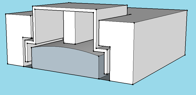
    For now, I'm planning on 3D printing the case and keycaps (even though I've done nothing of the sort). In the design, the key cap will be trapped between the case and the switch, with enough room to travel vertically to activate the switch.

    Hopefully this picture demonstrates the concept:


    I currently plan on using 3DS analog sticks. Unfortunately, it's not a very sustainable thing to design into an open hardware project, but I don't know where else to get nubs. Additionally, there is a software hurdle to make the microscontroller act as a USB mouse (joystick?) in addition to a keyboard. I have done very little with regards to USB, but it seems like it's possible to do using the standard HID interface.

    My hope is that these design logs leave breadcrumbs for people to follow if I don't personally finish the project, which is statistically likely for me :P

  • Power/Charging System Design Log 2

    Stephen M05/21/2015 at 06:28 0 comments

    Hello everyone,

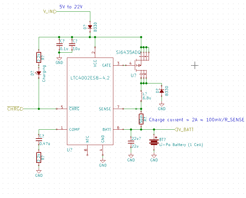
    Yesterday I decided on the LTC4002ES8-4.2 as the battery charger IC. It has all of the features I was looking for in a charger IC:

    • 2A charging current
    • Hand-solderable
    • Switching regulator
    • Fairly integrated (for a switching regulator)
    • Single cell charging
    • (Bonus) Charge indicator output

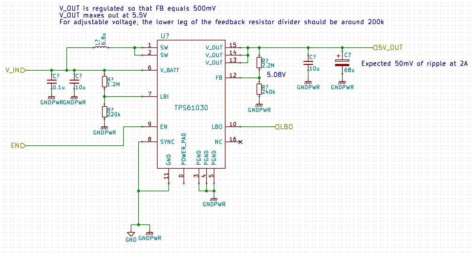
    As well, the main voltage regulator was chosen as the TPS61030. I was considering going with the TPS61032 which maxes out at 5V, but the TPS61030 (max 5.5V) allows me to set the voltage a bit above 5V to have a bit more ripple while staying above 5V. The voltage for the TPS61032 droops at higher currents as well. Based on the efficiency graph of the TPS61032 in the datasheet (no data for TPS61030), I'm expecting to get around 95% efficiency with the boost circuit while not powering external devices. I didn't spend too much time looking for other options: the regulator met my requirements and anything else would be for cost savings.

    The current version of the schematic can be found on GitHub.

    Thanks,

    Stephen

  • Now on GitHub

    Stephen M05/21/2015 at 06:06 0 comments
  • Power/Charging System Design Log 1

    Stephen M05/19/2015 at 16:33 0 comments

    Overview

    The power/charging system will provide 5V and the raw battery voltage to the other subsystems of the design (pi, display, and input). The rationale behind providing both of these voltages is that 5V will be the main power rail for the pi, external devices, and (likely) the input system, and the raw battery voltage will be used for boosting up or dropping down the voltage with greater efficiency. The raw battery voltage will be used for the step-up converter for the backlight , and will be locally regulated for (what will probably be) an FPGA to control the lcd.

    The power into the charging circuit will be provided by a micro-USB cable. There will also be a USB-A port which can provide power to external devices.

    Design Log

    The most concrete development so far is the choice of battery for the design. I have chosen this battery for the device. It's dimensions seem fairly ideal for the design. It will be able to fit underneath the pcb and beside the pi, while providing some room for taller components if needed, and it stores quite a bit of power to boot! There are a couple options for the termination of the leads, but bare wires simplify the BOM, are cheaper, smaller, and can be replaced by a battery with a JST connector later if necessary.

    Last night I spent quite a some time looking for battery charging IC's. Dave Jones has a video on li-po charging if you're interested. The battery I've chosen has a maximum charge rate of 2.5 A. Initially I was looking for a charger which would vary the current output based on the output of the load of the rest of the circuit. Most chargers, it seems, have the battery and load in parallel. If the charger is set to charge at 1.5 A in constant-current mode, and the load draws 1 A of current, the battery is only being charged at 0.5 A. Most, if not all, of the IC's with this feature are not hand-solderable (leadless or BGA packaged). I realized this morning that because the maximum charge current is so high (2.5 A), there are very few cases where the battery would discharge while a USB charging cable is attached.

    I have not found an IC yet, but now I know what I want, and sort-of what's available. It should charge at least at 1.5 A, be a switching type (to not produce as much heat as a linear regulator), work with a single-celled battery, and be fairly integrated (not too many peripheral components). I feel like it shouldn't be too long until I've found a good match.

    A bq2057 seems like it would work if I was willing to use a linear device rather than a switching device.

View all 10 project logs

Enjoy this project?

Share

Discussions

Similar Projects

Does this project spark your interest?

Become a member to follow this project and never miss any updates