Close
0%
0%

Home security

Home security project based on atmega and ardunio. MQTT gateway for data gathering.

Similar projects worth following
Home security project based on atmega and ardunio. MQTT gateway for data gathering.

This project should replace standard home security alarms, and And function as gateway to pass or receive data from various sensors. All configuration is done over nice web interface.

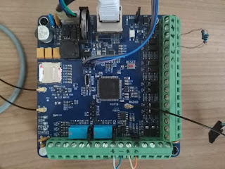
Gateway board consists of atmega1284P that has inputs for sensors and outputs to relays. It also hosts Wiz5500 Ethernet for configuration and overview, RFM69HW for radio remote nodes, communication module to wired nodes (RS485 protocol), GSM modem, Battery backed up RTC, EEPROM for log, I2C expansion connector, and AC supply and battery monitoring.

Gateway board has 8 analogue inputs that can recognize different events on PIR sensors, and 5 digital inputs. Inputs can be further expended.

Remote nodes act as authentication units or sensors. Currently they are set to receive iButtons as keys to arm/disarm the system.

All is now working and boards or PCB are fore sale!

  • 1 × ATMEGA 1284P custom main board Arduino environment compatiblie board with inputs outputs modified to work with sensors.
  • 1 × ATMEGA 328P custom entry board Arduino environment compatiblie board for remote enty.
  • 1 × Wiz5500 Ethernet connection.
  • 1 × RFM69 Electronic Components / Misc. Electronic Components
  • 1 × PIR sensors Any commercially available wired PIR Sensor.

View all 8 components

  • MQTT

    vysocan7604/08/2021 at 05:28 0 comments

    A new 1.3.1 version of gateway firmware is committed to GitHub which is enabling MQTT subscribe functionality.

    Gateway subscribe on topics: /OHS/set/#, particularly parsers following 

    /group /{#} - index of group {1 .. ALARM_GROUPS}   /state - allowed commands {disarm, arm_home, arm_away} /sensor - allowed only for Input nodes  /{address} - node address like W:2:I:D:1   /value - float value send to remote node  

    To describe it better for someone new to MQTT.  MQTT is an open OASIS and ISO standard,  lightweight, publish-subscribe network protocol that transports messages between devices. The protocol usually runs over TCP/IP. It is designed for connections with remote locations where a "small code footprint" is required or the network bandwidth is limited.

    /OHS/set/group/#/state topics is able to perform disarm, arm_home, arm_away commands for group index specified as #.

    /OHS/set/sensor/{address}/value topics is able to receive float number that is then passed to appropriate node address.

    Above subscribe and already existing publish functionality allow direct integration with mobile applications,  logging platforms for sensor data, or Home Assistant:

  • New board revison, bulk buy, discount on 2.0.4 gateway

    vysocan7601/16/2021 at 17:04 0 comments

    Last week I've received new 2.0.4 gateway boards. There are a few visible changes like connector description on silk screen and cut out hole for zip tie to hold on the RFM69 pigtail cable. And a few not so visible changes in routing and such, but none of them are really a reason to call it a new revision.

    One problem that I've started to realize is relatively pricier GSM modem. The 2G/3G/4G SIM7600x are starting at 40EUR for regional and 50EUR for Global band coverage. I was looking for some cheaper alternative while still keeping at least 4G, and the apparent replacement seemed to be a new SimCom A7670x. Unfortunately these use different package, and are only covering Europe and China, still I deiced to give it a go and spun new version of gateway. Just few day before sending it to fab I received a newsletter from SimCom that they released same modem called A7600E which is pin compatible to one that gateway already use (7600X). One difference it is still Europe only and only 2G/4G. I think it is reasonable as 3G is, at least in Europe, being replaced by 4G/5G networks. Good thing is it requires only one antenna and it is 5EUR cheaper. I've ordered 2 units to test them.

    For gateway, I have consolidated all the components, and I was able to get the price down by making bulk buy for all pricier components. Like buying the STM32F437 at RS Components, were it is 50% of my local distributor price.. This should reduce the final price to some 92EUR without a modem.

  • OHS 2.0.4

    vysocan7606/09/2020 at 11:27 0 comments

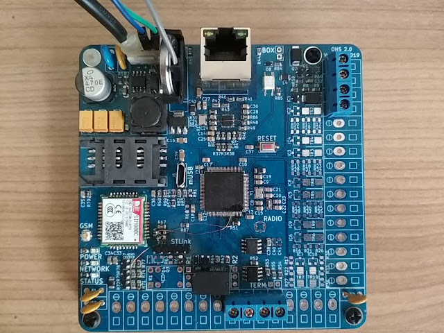
    Over past few months I have prepared new version of OHS gateway called simply 2.0.4. It is new iteration of my 2.0 version fixing layout defects and integrating new features. Here are the specifications:

    • STM32F407 with 1GB of flash and 128KB + 64KB CCM of RAM, running at 168MHz.
    • LAN8720A Ethernet PHY with 10/100Mbit.
    • Two step power supply with 12V to 3V8 switching and 3V8 to 3V3 LDO.
    • Battery for RTC CR2032. STM32F407 has on-board RTC.
    • 10 analog (balanced) inputs for PIR, smoke, ...
    • 4G SIM7600x module
    • Radio module for RFM69HCW, or alternatively RFM95.
    • 128KB SPI FRAM.
    • RS485 for wired connections.
    • 2 relays for sirens.
    • 1 tamper zone for enclosure. 
    • Micro USB port.
    • ST-LINK V2 port.
    • 3 LEDs.

    The main changes is GSM part, which now sports 4G/LTE modem from SIMCOM SIM7600x, and double the FRAM capacity.

    SIM7600x is decision that I've been thinking about for some time. On one hand the module is quite expensive compared to 2G modules, but on the other the 2G is becoming phase out in many countries. It is quite a dilemma, but I decided to invest into module that will have long life expectancy. There are always more difficulties. One is that the hardware needs to be able to speak with 1V8 logic presented on module, which I have solved by adding MOSFET level shifters. And second, that the module is bigger, and I neede to place it on the back of PCB. I have also removed the mini SIM holder, and replaced it with smaller and more up to date micro SIM.
    There are several versions of SIM7600 module. One global, most expensive, that is supposed to work in all regions. And the regional ones for Europe, North America, South America, Asia and so on.

    FRAM size has doubled for the reason to store some larger data needed conveniently.  First half (64KB) is used as before to keep 4096 log entries for gateway logger. Second half will be available to several new functionalities I plan to add to gateway software. I was also tmepted to add a uSD card, but it is easier to store data on synchronous SPI FRAM, then to access uSD with file system that can be damaged or not present. Not to speak about wiring.

    Other changes not so visible are RC circuits on battery and power signals of UPC. These are nicely filtering out the spikes that are sent to gateway, eliminating the need for software compensations. Without them the gateway has wrongly reported AC power OFF signal.
    Also there is now a shotky diode, to add polarity protection to RTC battery.


    Link to https://openhomesecurity.blogspot.com/2020/06/ohs-204.html

  • Gateway 2

    vysocan7609/15/2019 at 12:11 0 comments

    I did not post too much updates recently, but I was quite busy with new version of gateway. I manage to draw and let fabricate new PCB with 32bit ARM chip as main controller. For the purpose of first design I have shrunk the PCB to 100x100mm, but I have managed to squeeze all component I wanted there. Good news is that I was able to stay on 2 layers, and avoid much more expensive 4 layer PCB. I made the board at pcbway with the cheapest 6/6 method and the quality stays similar to my free boards. I will stay with them for sure.

    After realizing that 100x100mm PCB includes all I need, I will most probably stay with this new format. To sum up there is:

    • STM32F407 with 1GB of flash and 128KB of usable free RAM, running at 180MHz.
    • LAN8720A Ethernet PHY with 10/100Mbit.
    • Two step power supply with 12V to 4V switching and 4V to 3V3 LDO.
    • Battery for RTC CR2032. STM32F407 has on-board RTC.
    • 10 analog (balanced) inputs for PIR, smoke, ...
    • 2G SIM800C module
    • Radio for RFM69 or RFM95.
    • 64KB SPI FRAM, bit expensive, but no wait times and blazing speed compared to I2C EEPROM.
    • RS485 for wired connections.
    • 2 relays for sirens.
    • 1 tamper zone for enclosure. 
    • Micro USB port for firmware update and direct console access.
    • ST-LINK V2 port.
    • 3 LEDs.

    I guess it will pretty decent update to existing ATMega1284P.


    More on https://openhomesecurity.blogspot.com/2019/09/gateway-2.html

  • Preparation for new OHS gateway

    vysocan7602/03/2019 at 13:49 0 comments

    There is almost all functionality in OHS gateway that I have wanted when I started, however I have internal need to carry on :). One thing, I would like to improve, is the crypto capabilities that can never be achieved on otherwise very nice ATmega1284P 8 bit MCU. It somehow led me to look further into another step that would be 16 or 32 bit MCU. There are many choices in therms of available MCUs and platforms. Maybe to stay on Arduino platform and choose some of the ARM Cortex available. But I have decided to stay with older brother of now used NilRTOS called ChibiOS/RT, since the "operating system" RTOS is maybe the most important for me.

    ChibiOS can support variety of MCU including RaspberryPi and ATmega, but vast majority of supported MCU are STM32 families of many kinds. Looking at those mighty 32-bit ARM MCU, I have picked one called SMT32F407. These are high-performance Cortex-M4 32-bit RISC operating at a frequency of up to 168 MHz. They features a floating point unit (FPU), Ethernet, USB, RTC and so on. They have up to 1MB of flash storage and 128k of user usable RAM, and they are available in in various packages with varying pin count.

    My goal is to create new gateway with similar functions as the current ATmega one, and then build up on this.The gateway may have different number of hardware zones, but I want to use wire and wireless nodes and zones. That is, I intend to still use Arduino based nodes s much as possible, just because of their easy to use nature. I plan to add GSM module on gateway, maybe as add-on board, so it can be swapped to 4G module in future. And also wireless radio, maybe as add-on board too. SMT32F407 has software defined TCP/IP stack, and it can be used with IPv6, Web Socket, SSL/TLS and so on. And what I like most, as ChibiOS supports many more even higher performance MCU, the future grow will be then much easier.

    Saying all that I will continue to support, and develop new functionality on current ATmega gateway, as I use it at home :). The new one will not come anytime soon (this year), as it bring great deal of challenges in terms of HW and SW. Also I will keep the project open, as I do not like equipment that dies when its producer decides to cut it off, or just disable the required host server.

    https://openhomesecurity.blogspot.com/2019/02/preparation-for-new-ohs-gateway.html

  • New PCB review

    vysocan7601/21/2019 at 10:14 2 comments

    It is always nice when someone appreciate your work, especially if you give the product to public as free to use. It happened to me as well, I was asked to review a PCB fabrication house called pcbway.com. Without too much hesitation I have sent them Gerber files of OHS gateway, and two of weeks later postman brought me the package, nice :).

    I must say I have tried around 4 different China fabrication houses, and this one is fifth. I tend to do my board easy to hand solder, and I do not use fine traces or gaps bellow 10mils. This give me better trust to choose rather inexpensive manufacturing processes. There is not too much difference between ordering in pcbway and other houses, you do all as usual on their web pages. One difference though, is they probably inspect the gerbers by person. It came to me as I have used 6mil trace/gap option as the basic available, and within 1 day after submitting gerbers they proposed me to change it to 5mil. First time I've seen that actually someone had a glimpse of my layout before manufacturing. Of course it was a little more expensive, but still within the free coupon I was given for review.

    The boards themselves are nicely made. I can compare to 2 other PCB houses I have boards from. I will skip the traces evaluation since I have no visual or other tool to do any reasonable comparison. But first think you notice with bare eye is silk screen, it is noticeably vivid and precise. It's placement is usually the weakest point in China PCB houses. But this board is done accurately, not faint and not smeared. I think using this fab one can afford to put logo on silk screen and not be afraid that it will come out ugly.

    Second difference is via placement. When you use IC with many legs you usually route signals to other IC close to each other, this leads to having vias sit to each other in some pattern too. On such patterned vias you can easily spot the sharpness and bit placement. I must say there the vias on the PCB are great I would not be afraid to go with lower then my 0.3 millimeter.  Along with via quality goes actual hole placement. And it is similar to vias, nicely placed in exact center of pad.

    Third difference I've noticed is solder mask, using loupe the mask is somehow more corresponding to what is draw in gerbers. Put it simply, exposed copper pads are smaller and more precise. This will help especially during soldering, the small components will not wander around, and IC will not have as many solder bridges.

    Here is picture hopefully supporting my point, with pcbway PCB closer on top overlapping seeedstudio PCB. You can see here of-centered holes and wider solder mask along with nice silk text.

    As I said on beginning, I do not develop over-complicated PCBs with many layers, buried vias or impedance control, so my evaluation is as erudite as hobbyist can offer. But I would say I will use the pcbway services in future for sure.

  • Updates in 1.7.6.3

    vysocan7612/31/2018 at 08:01 0 comments

    New minor release is ready with following changes:

    • Full support for remote radio Authentication node including rather big change in RFM69 thread.
    • Update of WebUI, added JavaScript to Trigger menu to better show meaning of Pass option.
    • Update of WebUI, on Triggers and Timers overview. Many of the columns that are blocked via option, that is, they are now shown as blank instead of default for clarity.
    • Updated DigitalIO library most recent one and relevant OHS code.
    • Updated Ethernet library to most recent version (Now even newer Ethernet library available, need to do it again). 
    • Updated GSM library, there are some enhancements in parser.
    • Fixes in counting radio packets and other counters (++i vs. i++).
    • Few minor bugs fixed in WebUI.

    Compiled version: https://openhomesecurity.blogspot.com/p/firmware.html with link to GDrive.

  • New wireless mini node with RFM69

    vysocan7605/08/2018 at 06:03 0 comments

    Lately I have stared to play even more with various remote sensors wirelessly
    connected to OHS gateway. I have used my standard radio nodes, but its versatility is somehow to much for small wireless node. To save space and gain easier access to pins of MCU I have designed new node called Radio Node Mini. It resembles Arduino Pro Mini with ATmega328P, but it has place to mount RFM69 board on it. It also has micro USB connector for charging designed for 3.7 Li-Po or Li-On battery.

    It is breadboard friendly and measures only 24.4 x 32.8mm (0.96 x 1.29 in). All available pins are taken out to board sides and marked as on Arduino board. It is 3V3 board and it is available with 16Mhz or 8Mhz quartz oscillator. As it is made to work with Li-Po or Li-On battery it features battery voltage measurement on A6 via 2:1 voltage divider, and also ability to detect charging state connected to pin D8. Pin D2 is not taken out as it will be used as interrupt pin for RFM69. It has also possibility to assign pin D4 as reset for the RFM69 via solder jumper labeled RR. Board is programmable via FTDI programmer. Note, that it is not able to take power from micro USB without battery, the charger is providing only minimal current to the board when it does not detect the battery. However FTDI programmer can be used also as power source while developing.

    Board has excellent standby battery consumption within few uA when MCU and radio is asleep. It will last for months to year(s) depending on battery size and sleep conditions. Board is able to handle 500-2000mA battery. I especially like those flat 700-800mAh small quadrocopter batteries found on eBay. they are cheap, has similar size as the board, and have also protection circuit built in. Only drawback is that they have usually 100-150mAh less capacity then advertised.

    Boards are also now available in my store for 7EUR fully assembled. As option you can choose radio module, pigtail and antenna.

  • Wireless node configuration

    vysocan7601/20/2018 at 18:17 0 comments

    Wireless nodes are part of OHS ecosystem. They serve as source of data from sensors, and as receivers for inputs. Inputs represents relays or other devices waiting for incoming commands. If you want to connect wireless node to gateway you need to set it up first. Start with download of example sketch from GitHub. Here is code for hardware version 1.4 https://github.com/vysocan/remote_1_4_RFM69. If you have on hand version with on-board temperature sensor and USB charging circuit then you can use the code almost without change. Basically you need to modify just the setting for radio module. Here is the part for radio

    // Radio
    #define NODEID      14
    #define NETWORKID   100
    #define GATEWAYID   1
    #define FREQUENCY   RF69_868MHZ //Match this with the version of your gateway #define KEY         "ABCDABCDABCDABCD" //has to be same 16 characters/bytes on all nodes, not more not less!
    #define ENABLE_ATC  //comment out this line to disable AUTO TRANSMISSION CONTROL
    #define ATC_RSSI -75 

    From this you need to only change following:

    NODEID      2     // is number from 2 .. 250, do not number the nodes with same NODEID!
    FREQUENCY   RF69_868MHZ // depends on your country, leave it as is or put RF69_915MHZ
    KEY         "ABCDABCDABCDABCD" // needs to match the KEY of gateway.
    ENABLE_ATC        // leave as is for battery powered nodes
    ATC_RSSI -75      // threshold for AUTO TRANSMISSION CONTROL, you can safely leave as it is.

    To start with minimal changes only, change just NODEID to be unique and KEY to match the one from gateway.

    ...

    Read moire on blog: https://openhomesecurity.blogspot.cz/2018/01/wireless-node-copnfiguration.html

  • New major version 1.7.6.0

    vysocan7611/17/2017 at 05:28 0 comments

    Since summer time I was adding some features to gateway that led into new major version 1.7.6.0. Changes include:

    • Remote zones added.
    • Added group arm and disarm chain. That is when arming/disarming group by key, Gateway is able to automatically arm/disarm another group or groups.
    • Added group state MQTT publish. Gateway now, if enabled, will publish state of group via MQTT. Such information can captured by Home Assistant or other automation program.
    • MQTT sensor publish structure modified, added group name to path.
    • Updated MQTT library and MQTT protocol to 3.1.1.
    • Added new sensor type "Battery", to easily identify battery powered nodes voltage. 
    • Added new sensor type "Gas", to easily identify any air quality environmental sensor.
    • Added SMS command gateway. Authorized numbers from contact list are able to get Group state or set it On, Off, Arm and Disarm by sending SMS in predefine format to gateway GSM number. This functionality need some testing.
    • Updated NilRTOS to latest version available. In future port is needed to ChNil, which is newer replacement of NilRTOS, but unfortunately not one to one compatible with NilRTOS.
    • Various small enhancements in code and web interface.

    New version is now at GItHub.

View all 74 project logs

Enjoy this project?

Share

Discussions

gh349834 wrote 03/21/2022 at 11:24 point

Hey, that would be just a great and the best thing I have not seen before.

  Are you sure? yes | no

midnightcow wrote 11/21/2014 at 07:24 point
Hello,
Are you interested in the new WIZnet chip W5500 is more enhanced than W5200? If you want to have experience for W5500 and the related product as WIZ550io and ioShield, I will send it to you free.
WIZnet have the ethernet soultion as well as WiFi such as WizFi250.
Please feel free to contack to me. I will wait your reply.
Thank you.

  Are you sure? yes | no

midnightcow wrote 11/21/2014 at 07:27 point
I will send my email address to you with private message. Please read the message.
Thank you.

  Are you sure? yes | no

vysocan76 wrote 11/21/2014 at 08:02 point
Hello, that would be just great :) I will be happy to test it and use it. I can send you some boards in return.

  Are you sure? yes | no

midnightcow wrote 10/06/2014 at 23:41 point
Hi, vysocan76.
Good Job!!!
I am working in WIZnet, and working hard to activate forum(wizwiki.net/forum).
I am interested in your project, I find what I can help you.
If you need my help, feel free contact to me.
Thank you

  Are you sure? yes | no

vysocan76 wrote 10/07/2014 at 07:22 point
Hello midnightcow,

thanks for interest, that is just great. I have problem with wiz820io. I have found that the wiz820io is not recovering correctly on power failure. There is need to reset whole board manually after power on. I have the wiz820io reset pin tied to atmega reset.
I was thinking to add reset watchdog to the board, but haven't had time to test yet. Or to use INT wiz820io pin which I have connected to atmega, and it is not used by driver for software reset.

  Are you sure? yes | no

midnightcow wrote 11/06/2014 at 01:35 point
Hi,
As you mentioned before, WIZ820io(W5200)'s reset pin had better to connect to AVR's GPIO. Because W5200 need over 150ms for reset after RSTn goes high. Also, The RESET low time maybe over 20us.
For more detail, refer to W5200 datasheet. You can see at http://www.wiznet.co.kr/Admin_Root/UpLoad_Files/BoardFiles/W5200_DS_V130E.pdf
I expect that you will process your project very well.
Thank you.

  Are you sure? yes | no

vysocan76 wrote 11/11/2014 at 10:37 point
Hello, thanks for the link. I have used reset watchdog, First test are OK. You can look for updated schematics on my blog.

  Are you sure? yes | no

midnightcow wrote 11/13/2014 at 02:02 point
Hello,
I saw the updated schematics, MCP130 satisfied the low time of W5200 RESET.
Becaue W5200 need to the time over 150ms after RESET high, MCU should wait the time. If you will implement the firmware, you will check the time.
Thank you and have a nice day!!!.

  Are you sure? yes | no

vysocan76 wrote 11/19/2014 at 15:17 point
Hello, not sure what you mean that I whould implement the time in the firmware. I believe that the MCU stays in reset state together with W5200 chip. Can you elaborate more on this.
Thanks ...

  Are you sure? yes | no

midnightcow wrote 11/21/2014 at 03:58 point
Hello,
I don't have your board, so i can't elaborate it. But i will check the reset high time on your github source codes.
Thank you.

  Are you sure? yes | no

midnightcow wrote 11/21/2014 at 07:13 point
I was checked the code - setup() in main_board.cpp. Becase Ethernet.begin() was called after low speed device as EEPROM and Serial is begined, I think that W5500 reset high time is garanteed.

  Are you sure? yes | no

Similar Projects

Does this project spark your interest?

Become a member to follow this project and never miss any updates