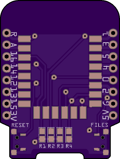
I still didn't get the flash to work correctly, but I had some sleepless night, so I sketched up a PCB for the first prototype. This is the top where the ESP-12F module goes:

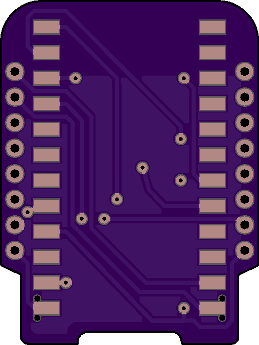
And this is the bottom, where a Pro Micro goes:

There is also an extra button on the opposite side than the reset, for selecting the USB mode. That's pretty much it, since the Pro Mini already hast he voltage regulator and all that, and the programming pin can be held down by software.
 deʃhipu
Discussions
Become a Hackaday.io Member
Create an account to leave a comment. Already have an account? Log In.
Do you worry about vias underneath the ESP-12F possibly shorting? I feel safer with at least a layer of soldermask on there.
Are you sure? yes | no
In the worst case I will put some kapton tape under the module. Making blind vias in Fritzing is a bit of a chore, and this is just a prototype anyways.
Are you sure? yes | no
Yes, kapton is a good idea. I asked because I have a PCB design with the ESP-12x that just came back today ready for soldering. It's just a boring switching regulator test, though :-)
Are you sure? yes | no