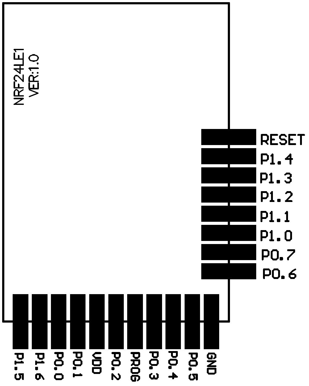
Now connect the two modules to the Raspberry Pi.
I'll make a diagram of the connections but meanwhile I'll leave the list of connected pins (this module uses the 32 pin version):
nRF24 - Raspberry GPIO
FCSN (P1.1) - 8
FMISO (P1.0) - 9
FMOSI (P0.7) - 10
FSCK (P0.5) - 11
PROG - 24
RESET - 25
Finally, the GND and 3.3v and that's it.

Also, on the Raspberry, download the necessary libraries, SDK and some examples:
This page has the necessary information although some bits are not quite well explained but you can get the big picture:
http://sysmagazine.com/posts/210974/
Also has a code example "led_delay" that will blink a led on pin P0.0. This helps to test the programmer and then compilation platform.
 Rui Rex
Discussions
Become a Hackaday.io Member
Create an account to leave a comment. Already have an account? Log In.