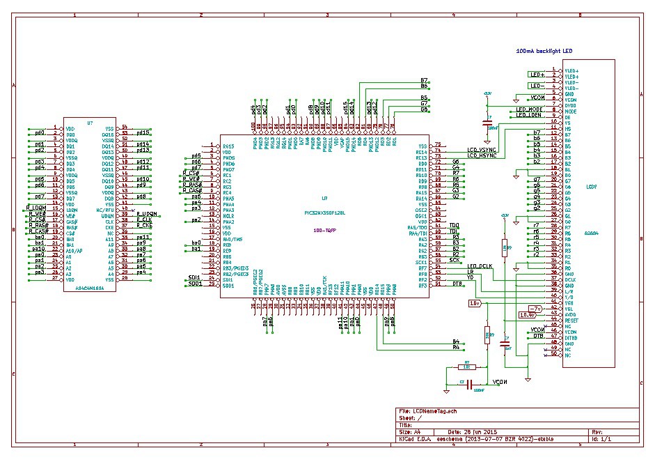
Here's an incomplete schematic:

A couple tips for producivity:
MPLAB Harmony (and the Configurator for some smaller PICs) have a pin diagram that you can use to figure out where modules are and line up what goes on your PIC without absolutely scouring the datasheet. Looks neat so far. I'll use it later for code too.
KiCAD parts can be slow to generate, so I use an online "quicklib" tool here http://kicad.rohrbacher.net/quicklib.php. Not as good as getting free Eagle parts, but it fits into the KiCAD design regimen well and I get to customize things at every step.
Now, the ram chip has a clock pin which I hadn't figured on. The PIC PMP might be able to use a chip select pin sort of as a clock, not sure, need to read more. An annoying placement too, I was figuring to use PORTD as most of the LCD color specifying bits.
Also, 24 bits of connection is way more than I want to actually do now that I look at it in the project. The PIC port pins don't line up and it's a struggle to use only 3 different ports to make these 16 bits work. I think this will be plenty.
It's frustrating but it's interesting! But I'm getting burned out for this weekend.
 Depot
Depot
Discussions
Become a Hackaday.io Member
Create an account to leave a comment. Already have an account? Log In.