 Clovis Fritzen
I have decided to start designing the voltage analog inputs' circutry for the datalogger; I will not worry with current inputs or themocouple inputs for now, since I have not even validated the basic concept :) . That's work for the future.
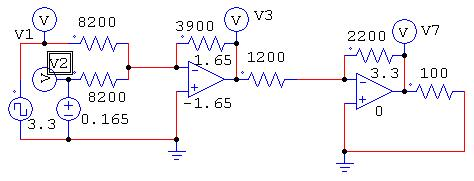
I have selected 3 ranges of voltage input to begin working on: 5V, 50V and 400V (DC). Every range will have an opamp circuit (picture below) to adjust gains and voltage levels. The signal 'V1' in the very left is the input voltage and signal 'V7' is the voltage being applied to the controller (Teensy LC).
The first stage is an inverter and multiplier, which makes a 0-3.3V into a 0.165V-1.65, while the second stage transforms the prior voltage into a 0.3-3V for the Teensy LC analog input.
I will keep you posted on advances I make and new features I implement!.
Discussions
Become a Hackaday.io Member
Create an account to leave a comment. Already have an account? Log In.