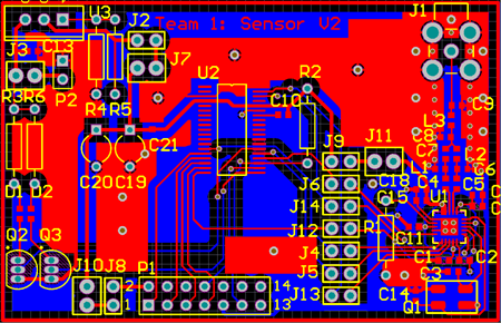
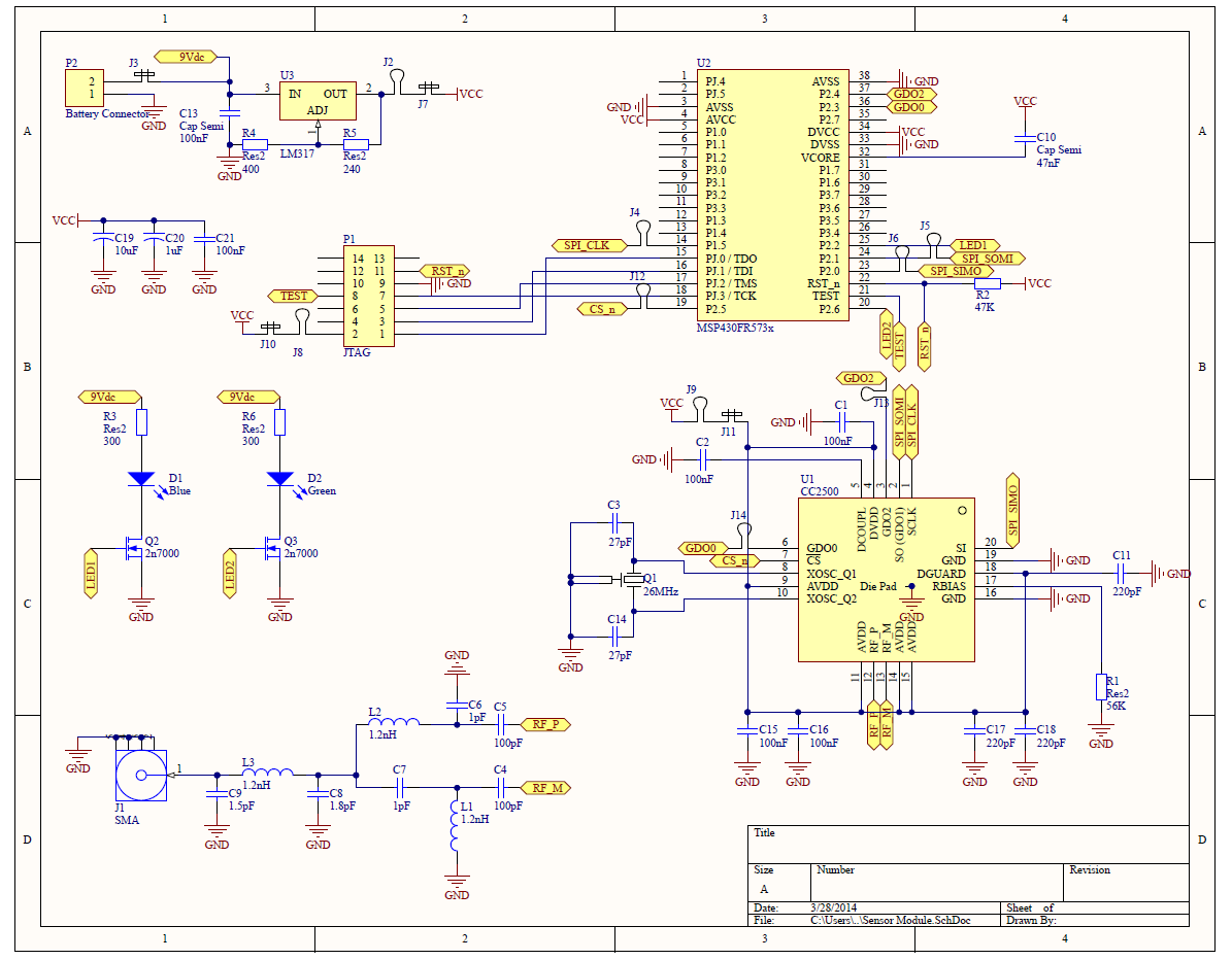
I made some rough PCB prototypes for the board a while ago, just to test the radios, micro-controller and firmware together. You can see a picture of the Altium board file below. I had the Electrical Engineering Department at my school (Texas A&M) mill the PCB to test. If the PCB works as expected, I will modify the board and send out to OSHPark (or similar) for a more professional run.
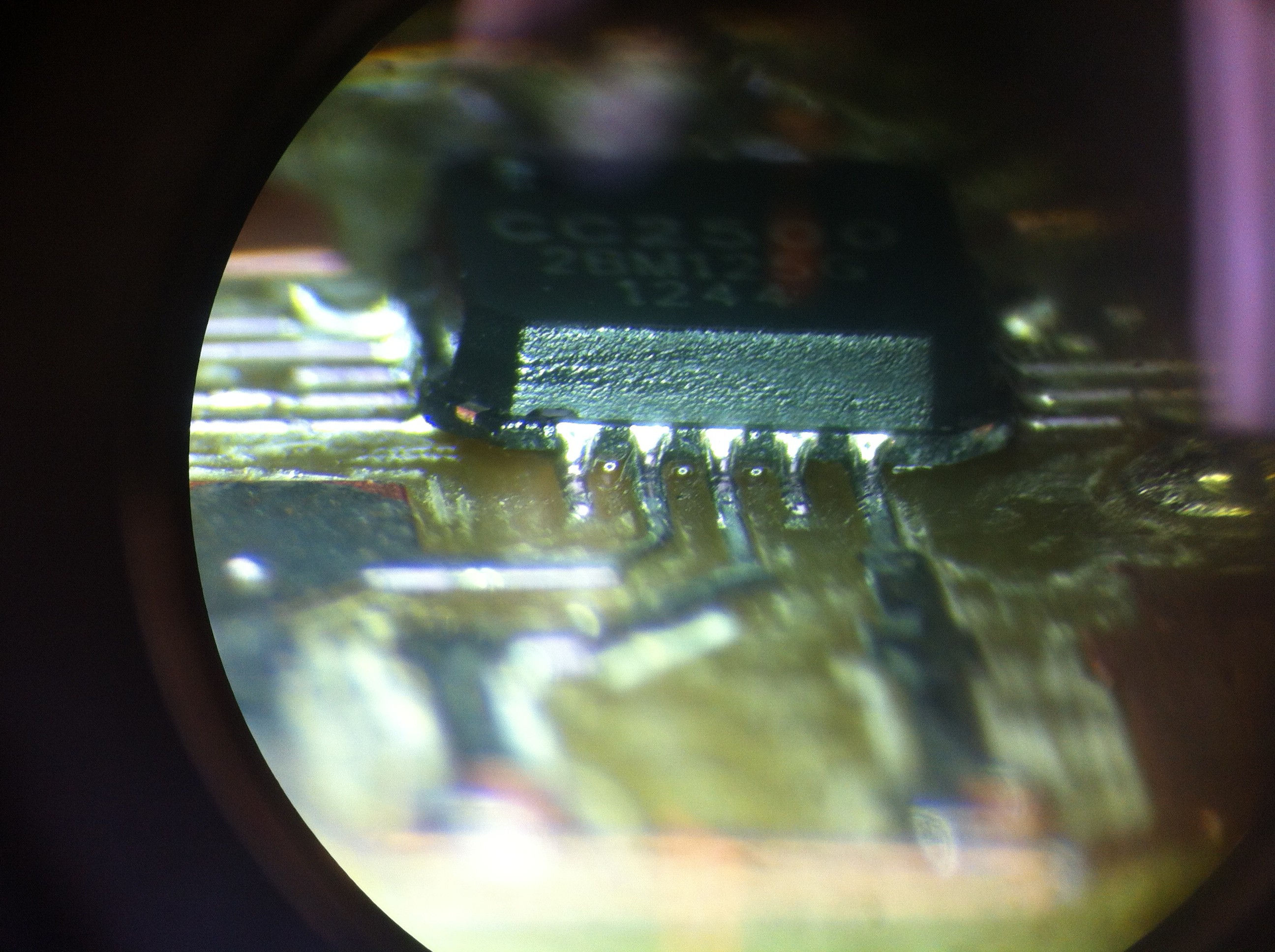
I spent hours soldering the tiny SMD components on (0402 SMD inductors, 0603 SMD Caps, etc), especially the CC2500 which I was only able to get in a QFP package.
This little fella was NOT easy to hand solder! You may n
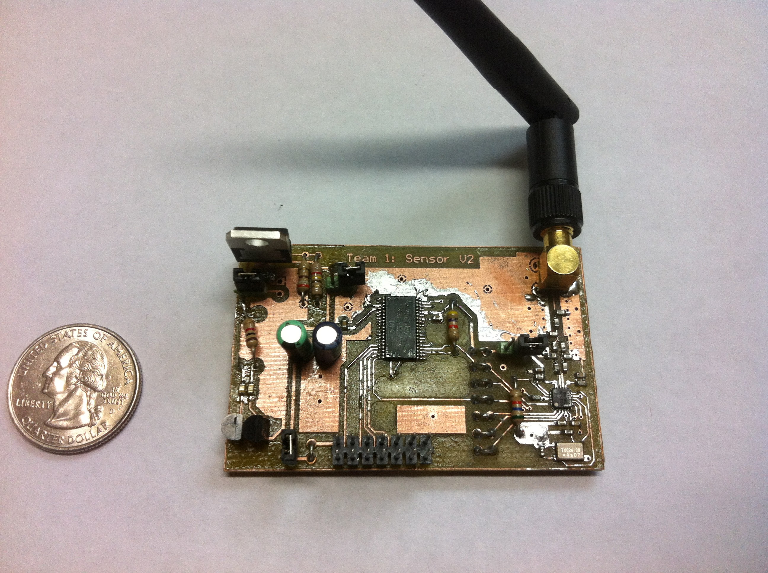
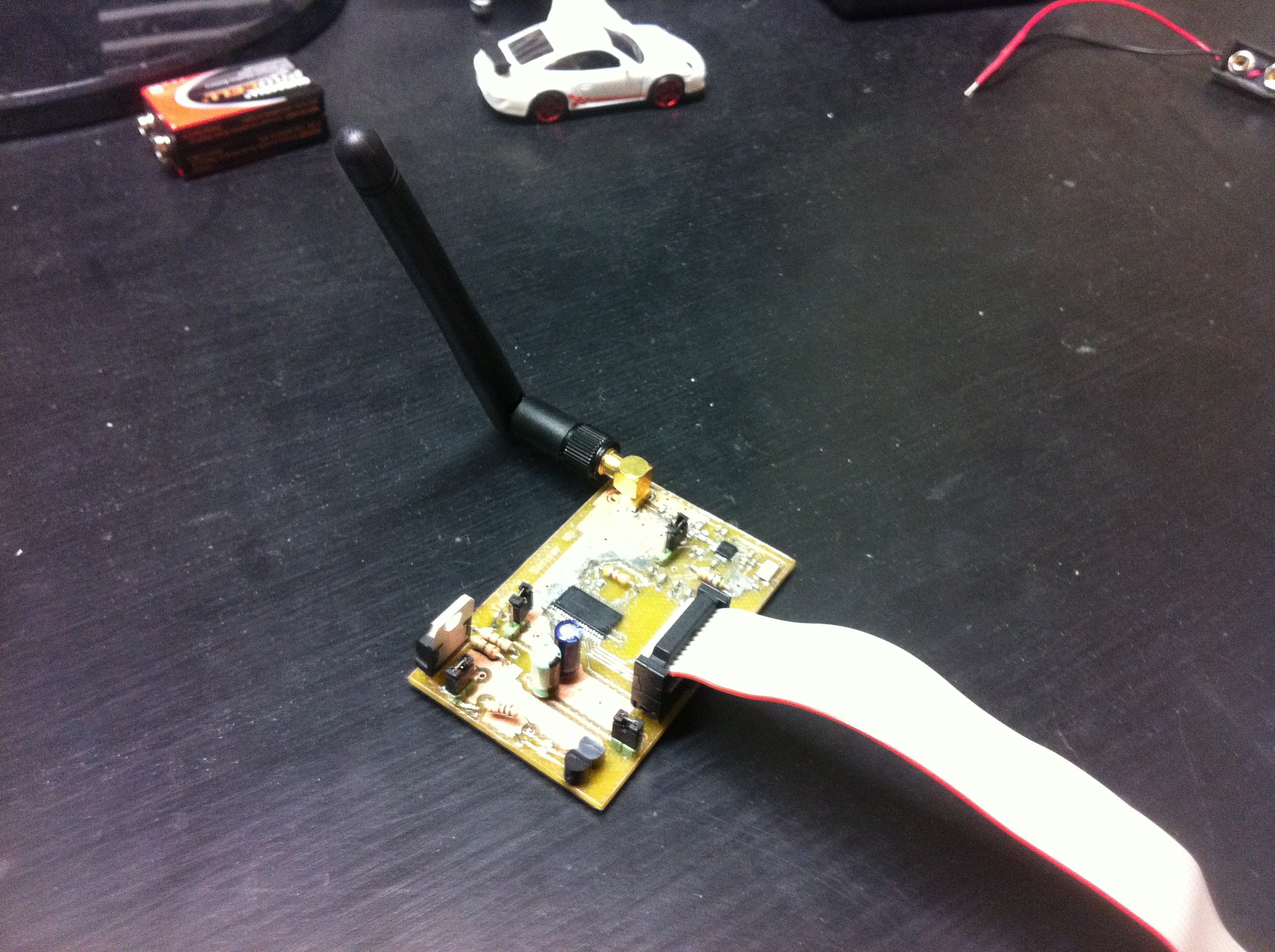
Here are some pictures of the board soldered up and ready for programming and testing.
I have a lot of extra test loops and jumpers in this circuit for debugging, but my final circuit will not have any.
 John Boyd
Discussions
Become a Hackaday.io Member
Create an account to leave a comment. Already have an account? Log In.