Close
0%
0%

Tote

Affordable spider robot

Similar projects worth following
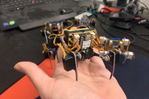
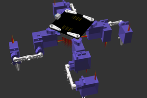
Tote is a four-legged, spider-like robot designed as a cheap and simple base for experiments with walking robots. It's easy to make, but very easy to modify and extend.

I'm writing a detailed instruction manual describing how to make it and how it works,.

The manual guide is available at http://tote.rtfd.org

Where are my robots? It's already 15 years into the twenty-first century, and we still don't have robots everywhere. Sure, there are some simple vacuum cleaners and some robo-pets for the ultimate geeks, but that is not enough! Especially since the vacuum cleaners don't even walk. We need more walking robots everywhere!

I think that one of the reasons why we don't have robots creeping and crawling all around us is that researching walking robots is a time-consuming, hard, and very expensive activity, traditionally confined to the secret military laboratories. You need a big room with a crane to hang your robot on, in case it falls, you need lots of hydraulic actuators and a pump to power them, you need sophisticated sensors and complex algorithms crunched on powerful computers, etc. At least that's how it has been so far. Even building a simple hexapod from a kit, which, is not much more than a simple toy, can set you back hundreds of dollars. No wonder we make no progress.

That has to change. If we put a walking robot on the desk of every high school student out there, and let them try hack on them and try the craziest ideas, sooner or later someone will come up with a bunch of cool tricks that let you solve that leg trajectory optimization problem on an Arduino at 50Hz a second, instead of a supercomputer crunching on a single frame whole day. We have a lot of corners we can cut there. Plus, those same high school students are likely going to continue their experiments and research and graduate in robotics and build us that robot butler that we always wanted. Or something.

So that's my plan with Tote. To solve the humanity's burning problem of glaring lack of robots, I'm working on a robot that is suitable as a base for experimenting with robot gaits and related problems.

View all 14 components

  • Reviving the Skull Tote

    deʃhipu06/07/2018 at 19:04 0 comments

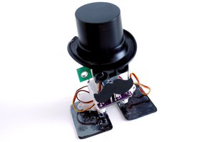
    I have a number of prototypes of Tote that I have built over the years, but the most presentable one is the one I pimped up in https://hackaday.io/project/6050-tote/log/48853-pimp-your-bot

    Unfortunately, that robot had a number of problems. Unlike all other Totes, it was powered with a 2S lipo battery, with a buck converter bringing to voltage down to 5V. That tiny buck converter would only work for a few minutes, and then starting to shut down when the current drawn by the servos made it too hot. Which would result in the robot having a seizure. I also discovered that the motor in one of the servos got stuck — rather common with the cheap SG90 servos — and would need to be replaced.

    So I decided to open up this robot, replace the power with a more standard setup (a 1S lipo connected directly without any voltage stabilization), add a battery charging circuit, and replace the servo.

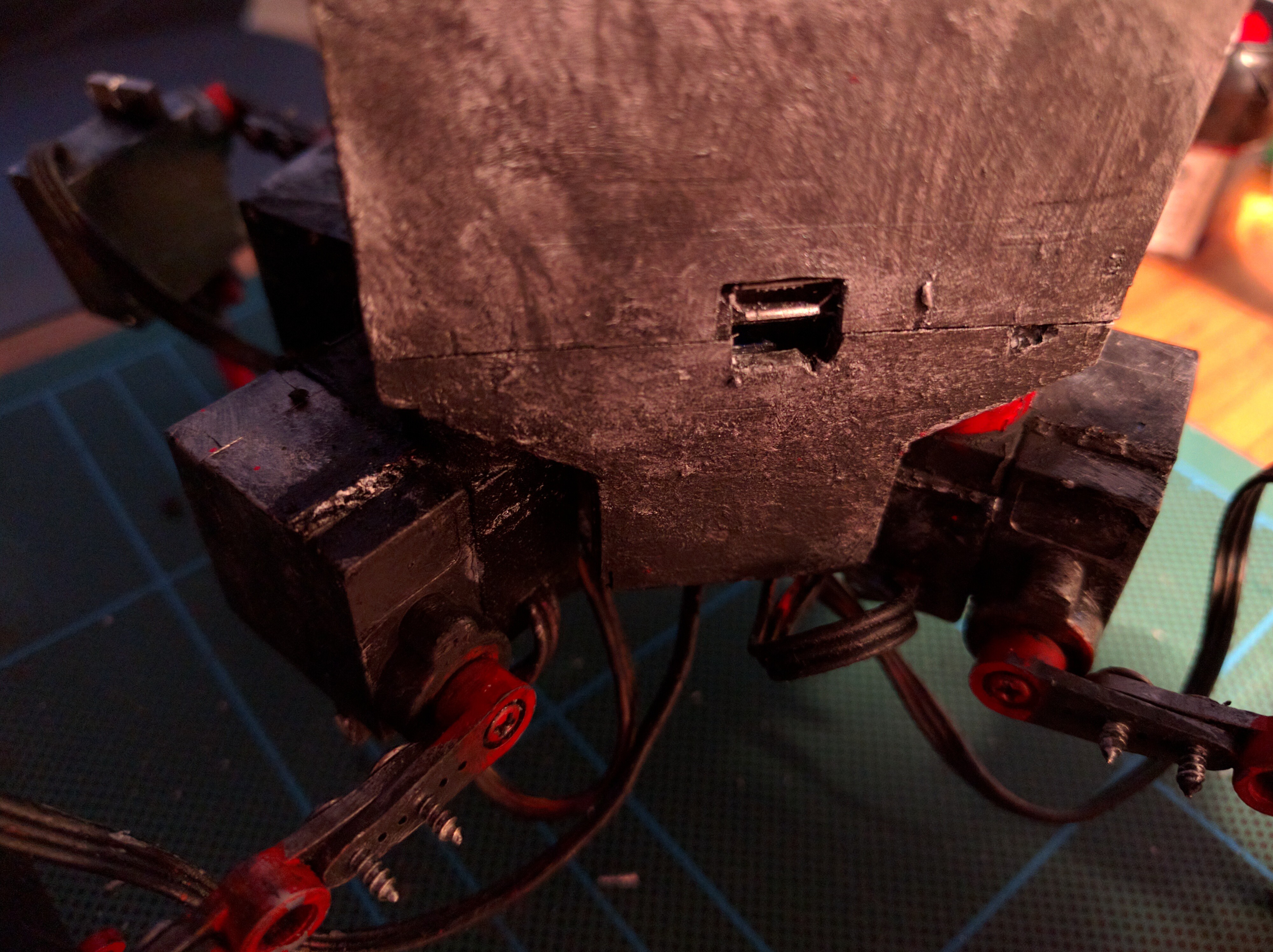
    Here's the USB port for the battery charging circuit:

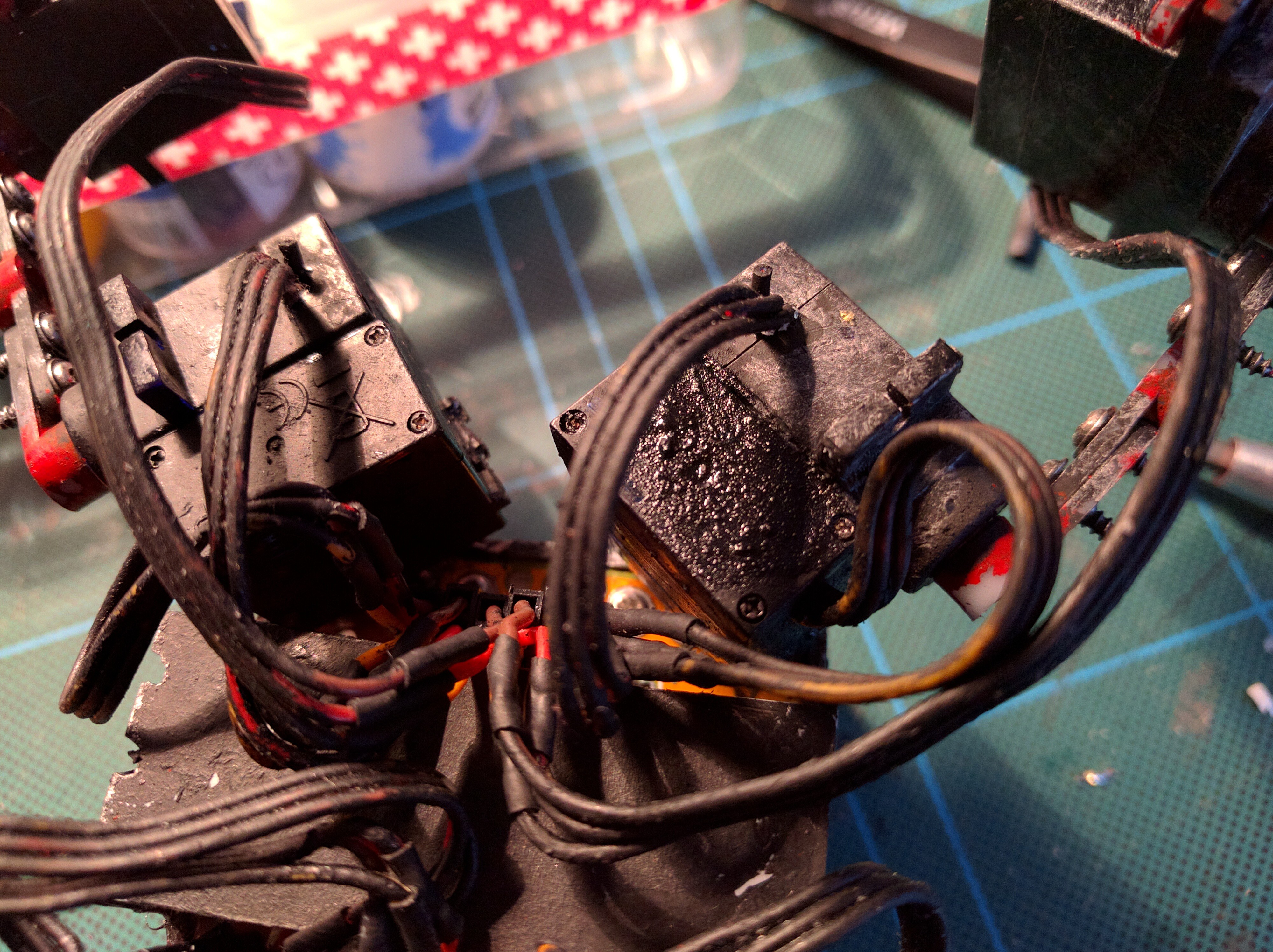
    And the replaced servo, primed with black paint, waiting to dry for a dry-brushing:

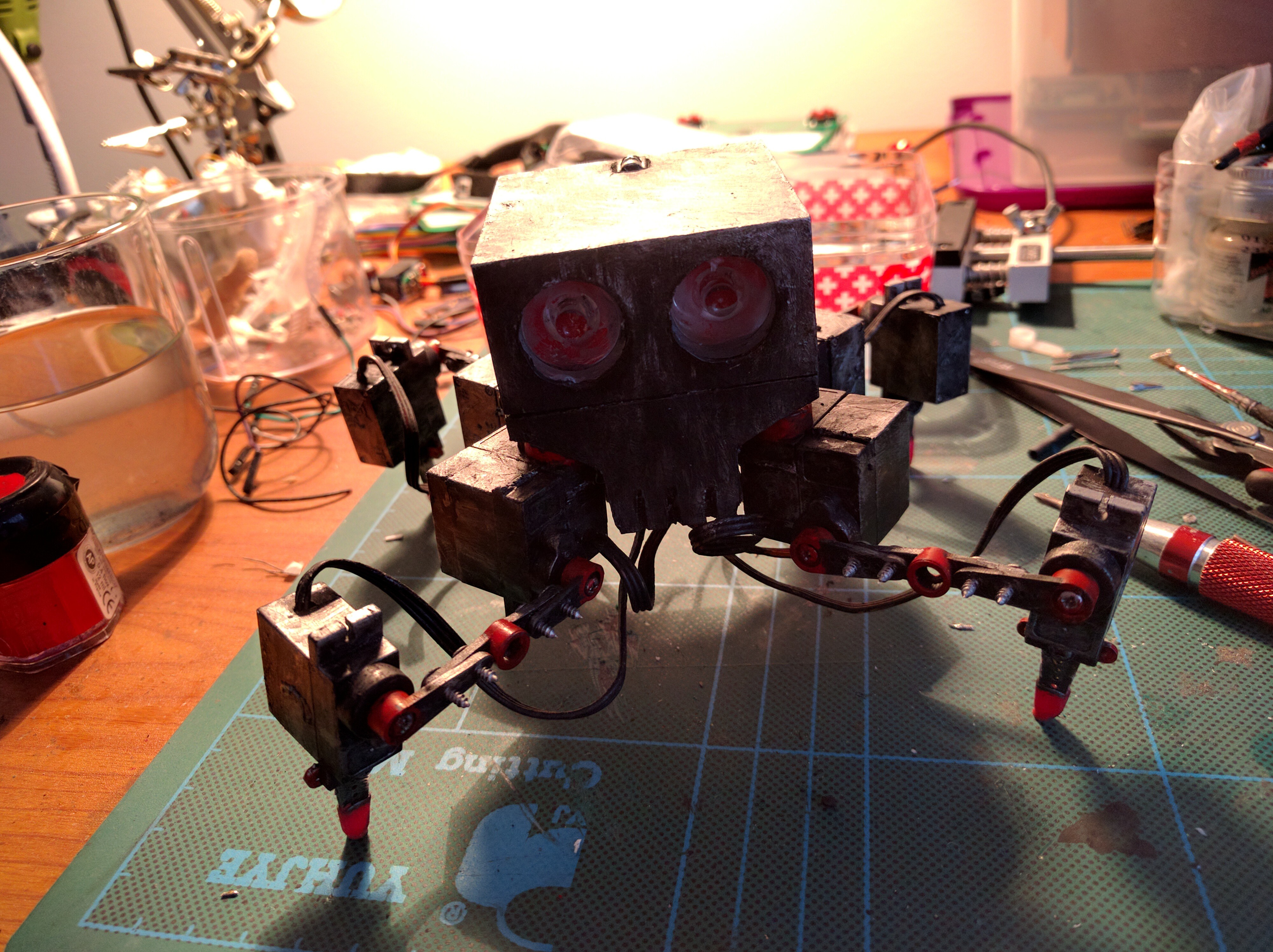
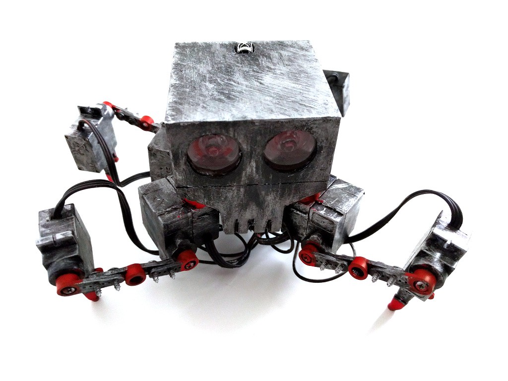
    And finally the whole robot, it all its robot glory:

  • Gangsta

    deʃhipu01/15/2017 at 11:34 2 comments

    As I wrote in the previous logs, I'm going to be upgrading Tote to use some more expensive, but more powerful and easier to use components. But what about the poor students? If you are really concerned about the budget, the original Tote is almost what you need. Almost, because you would still need to order the PCB for it. Or would you?

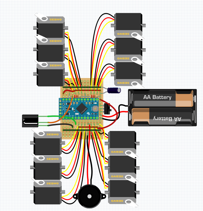
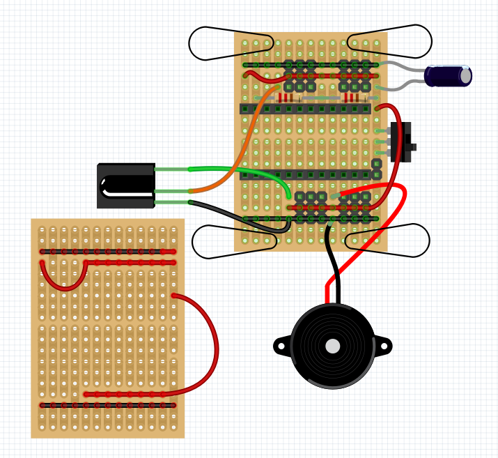
    Of course not! The PCB doesn't have anything you can't easily reproduce on a vero/strip/perma board! Here's one example of a Tote on a strip board:

    Sure, you will need to remap the pins in the code, but that should be quite easy. Yes, I went wild in Fritzing, and it's barely readable. Here's a clearer picture of the strip board you will need to make:

    It even has the voltage divider for monitoring the battery. Oh, right, and don't use alkaline batteries like on the picture. Use a LiPo from a quadcopter or from an old cellphone.

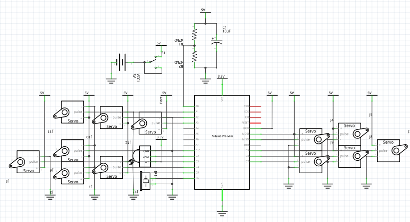
    I have to admit that one thing they say about Fritzing is true: it sucks for making schematics:

    I wonder if I should fork this version off the main Tote, and keep a repository with the Arduino code for it, with remapped pins and so on...

  • Programming the Spinal Cord

    deʃhipu01/14/2017 at 14:11 0 comments

    n the previous log I made a decision to use an Adafruit Feather board for the robot's brains, and a bare ATmega chip in a DIP package for its spinal cord -- that is, the servo controller. That's supposed to make the board much easier to solder even by inexperienced builders. But wait a minute! How are they going to get the servo controller program onto those chips? Will that not require some extra hardware? Sadly, yes.

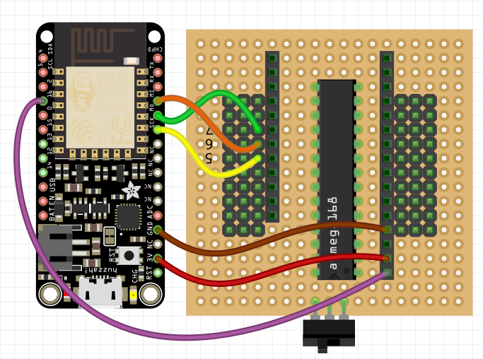
    It will require six extra wires.

    The trick is to use the Feather board as an ISP programmer, using the "Arduino as ISP" example sketch from the Arduino IDE. You will need to make the following connections:

    Now, in your Arduino IDE go to Files→Examples→11.ArduinoISP and select that example. Then scroll to around line 68 and change this:
    // Configure which pins to use:
    
    // The standard pin configuration.
    #ifndef ARDUINO_HOODLOADER2 
    
    #define RESET     10 // Use pin 10 to reset the target rather than SS
    #define LED_HB    9
    #define LED_ERR   8
    #define LED_PMODE 7
    Into this:
    // Configure which pins to use:
    
    // The standard pin configuration.
    #ifndef ARDUINO_HOODLOADER2 
    
    #define RESET     0
    #define LED_HB    2
    #define LED_ERR   4
    #define LED_PMODE 5
    Then go to Tools→Board and select the Adafruit HUZZAH board, then do Sketch→Upload. You have your programmer ready.

    Then to program the chip, load the sketch with the servo controller, change the board to Arduino Uno, select Tools→Programmer→Arduino as ISP, and do Sketch→Upload Using Programmer. You should see some blinking lights on your Feather, and then your chip is programmed.

    In the end, I will probably make a Makefile that does the equivalent of the above procedure automatically, to streamline the experience a bit.

  • Choosing the Brains

    deʃhipu01/11/2017 at 22:28 4 comments

    In the previous post I shared some of my thoughts about this project, and decided to pick a different development board than the Pro Mini that I have been using so far. Don't get me wrong, Pro Mini is great for all kinds of small and cheap projects, it's just that I want to make programming this robot as simple as possible. That, among other things, means using a platform that has a lot of computing power, not just enough, preferably one that has so much of it, that it can be used with a high-level language like Python. That also means something that has a USB socket.

    Read more »

  • New Year Reflections

    deʃhipu01/11/2017 at 16:15 0 comments

    Year's Summary

    This is one of my oldest projects, and definitely one that I have put the most total work into so far. With the year's end, I decided to reflect a bit about the progress made so far and the way forward.

    There wasn't a lot of activity, but some interesting things did happen last year.

    We had a workshop in Belgrade, where we built 20 #Tote HaDs. I have learned a lot about how (not) to source parts for such an event, how to run it, what parts are actually hard for people, etc. There were also some improvements to the construction itself contributed by the participants -- but only during the workshop. I'm a bit disappointed that nobody seems to have done anything with their robot after the workshop -- or, at least, I haven't heard about it. I think this is an important point to consider.

    There have also been some Tote-inspired builds out there. I helped to build at least two of them. There are even more unfinished projects, but I guess that's normal.

    On my side, I released another version of the PCB, experimented with some alternate brains (including the #Tote Zero with a Raspberry Pi), and made one of my prototypes look much better by giving it a chassis and some LED eyes, and a coat of paint. There has been practically no progress on the software side, despite some research on the CORDIC algorithms and servo PWM code. I also didn't experiment much with sensors and behaviors. The step-by-step tutorial is also empty.

    Overall, even though some work got done, and even though I gained some experience, I'm not particularly happy with the outcomes of the Tote project. I'm starting to realize that it's not enough to give people a platform to experiment with -- even if they do experiments and improvements, it's all for nothing if they don't share them.

    Wrong Goals

    I think that part of the problem is that I have been focusing on the wrong parts of the project. I need to pause and re-evaluate some of the assumptions I made, and see where that takes me.

    When I was just starting with Tote, I still remembered being a student and not having much of a budget for this kind of projects. So I made lowering the total cost the number one priority (well, apart from having it actually work, of course). As I look at this now, this might have been a mistake. Sure, when you are a student in Poland, price is the number one factor for anything. But it turns out that most people who do this hobby stuff actually don't mind spending a little bit more if that saves them time, makes things more convenient, gives better results or even just makes things look more shiny. If you are going to put hours of work into a project anyways, you don't mind waiting a little bit more to get the extra funds. So I am going to pay less attention to the price (but still try to keep everything frugal) from now on.

    By default, Tote is controlled with a TV remote, and has no autonomous functionality. I did that, because I figured it's the simplest starting point, and also shows off the hardware capabilities, leaving any software-side innovation to the users. Or maybe I was just lazy. In any case, I think that this has turned it into a toy, and discouraged actually programming it. There are some other decisions that also contributed to it: the need for an external programmer for programming, the main code written in C++, no easy way to update and debug the code. I think I should start putting more effort into making it easier to actually program this robot, and encourage it more. Fast iteration is the key to good progress. I have become painfully aware of that recently when working on the recent version #µBob biped robot, where I had to physically unscrew and detach the legs to access the chip for programming. That's the best way to make sure nobody ever changes anything in the program unless they absolutely must. So I need to try and remove all the obstacles for programming. And also finally finish the programming tutorial for it.

    Simplicity was another design goal (it always...

    Read more »

  • imath.h

    deʃhipu12/22/2016 at 14:48 0 comments

    It took me two evenings of pretty much randomly editing code, trying to make it as small as possible without breaking it horribly at the same time, but I finally have a library with three basic functions, iasin, iatan2 and isqrt, which are int16_t versions of the ones from the standard library. The angles are returned in the range of -1800 to 1800, and the input to asin is -1<<13 +1 to 1<<13. The whole library is around 700 bytes (644 at the last compile) and should be relatively fast on the AVR (although I didn't really time it). Oh, and the code is at https://bitbucket.org/thesheep/imath/src/tip/imath.c

    If you see any opportunity to shrink it even more, please tell me!

    Unfortunately, this is still way too large to make Tote fit in the magical kilobyte. I might try with int8 versions next, but those are not going to have enough resolution for a proper walk, unless I will play with the ranges some more.

    Here's a comparison of the values from those functions with the standard library:

    asin(-0.88)=-61.04 iasin(-7168)=-610 diff -0.04
    asin(-0.75)=-48.59 iasin(-6144)=-486 diff 0.01
    asin(-0.63)=-38.68 iasin(-5120)=-388 diff 0.12
    asin(-0.50)=-30.00 iasin(-4096)=-302 diff 0.20
    asin(-0.37)=-22.02 iasin(-3072)=-220 diff -0.02
    asin(-0.25)=-14.48 iasin(-2048)=-144 diff -0.08
    asin(-0.12)=-7.18 iasin(-1024)=-70 diff -0.18
    asin(0.00)=0.00 iasin(0)=0 diff 0.00
    asin(0.12)=7.18 iasin(1024)=72 diff -0.02
    asin(0.25)=14.48 iasin(2048)=144 diff 0.08
    asin(0.37)=22.02 iasin(3072)=220 diff 0.02
    asin(0.50)=30.00 iasin(4096)=300 diff 0.00
    asin(0.63)=38.68 iasin(5120)=388 diff -0.12
    asin(0.75)=48.59 iasin(6144)=486 diff -0.01
    asin(0.88)=61.04 iasin(7168)=610 diff 0.04
    asin(1.00)=90.00 iasin(8192)=916 diff -1.60
    
    sqrt(0)=0.00 isqrt(0)=0 diff 0.00
    sqrt(1024)=32.00 isqrt(1024)=32 diff 0.00
    sqrt(2048)=45.25 isqrt(2048)=45 diff 0.25
    sqrt(3072)=55.43 isqrt(3072)=55 diff 0.43
    sqrt(4096)=64.00 isqrt(4096)=64 diff 0.00
    sqrt(5120)=71.55 isqrt(5120)=71 diff 0.55
    sqrt(6144)=78.38 isqrt(6144)=78 diff 0.38
    sqrt(7168)=84.66 isqrt(7168)=84 diff 0.66
    sqrt(8192)=90.51 isqrt(8192)=90 diff 0.51
    
    atan2(0, 0)=0.00 iatan2(0, 0)=0 diff 0.00
    atan2(0, 1024)=0.00 iatan2(0, 1024)=0 diff 0.00
    atan2(0, 2048)=0.00 iatan2(0, 2048)=0 diff 0.00
    atan2(0, 3072)=0.00 iatan2(0, 3072)=0 diff 0.00
    atan2(0, 4096)=0.00 iatan2(0, 4096)=0 diff 0.00
    atan2(0, 5120)=0.00 iatan2(0, 5120)=0 diff 0.00
    atan2(0, 6144)=0.00 iatan2(0, 6144)=0 diff 0.00
    atan2(0, 7168)=0.00 iatan2(0, 7168)=0 diff 0.00
    atan2(0, 8192)=0.00 iatan2(0, 8192)=0 diff 0.00
    atan2(1024, 0)=90.00 iatan2(1024, 0)=899 diff 0.10
    atan2(1024, 1024)=45.00 iatan2(1024, 1024)=449 diff 0.10
    atan2(1024, 2048)=26.57 iatan2(1024, 2048)=274 diff -0.83
    atan2(1024, 3072)=18.43 iatan2(1024, 3072)=183 diff 0.13
    atan2(1024, 4096)=14.04 iatan2(1024, 4096)=139 diff 0.14
    atan2(1024, 5120)=11.31 iatan2(1024, 5120)=112 diff 0.11
    atan2(1024, 6144)=9.46 iatan2(1024, 6144)=95 diff -0.04
    atan2(1024, 7168)=8.13 iatan2(1024, 7168)=84 diff -0.27
    atan2(1024, 8192)=7.13 iatan2(1024, 8192)=70 diff 0.13
    atan2(2048, 0)=90.00 iatan2(2048, 0)=899 diff 0.10
    atan2(2048, 1024)=63.43 iatan2(2048, 1024)=633 diff 0.13
    atan2(2048, 2048)=45.00 iatan2(2048, 2048)=449 diff 0.10
    atan2(2048, 3072)=33.69 iatan2(2048, 3072)=336 diff 0.09
    atan2(2048, 4096)=26.57 iatan2(2048, 4096)=274 diff -0.83
    atan2(2048, 5120)=21.80 iatan2(2048, 5120)=216 diff 0.20
    atan2(2048, 6144)=18.43 iatan2(2048, 6144)=183 diff 0.13
    atan2(2048, 7168)=15.95 iatan2(2048, 7168)=159 diff 0.05
    atan2(2048, 8192)=14.04 iatan2(2048, 8192)=139 diff 0.14
    atan2(3072, 0)=90.00 iatan2(3072, 0)=899 diff 0.10
    atan2(3072, 1024)=71.57 iatan2(3072, 1024)=724 diff -0.83
    atan2(3072, 2048)=56.31 iatan2(3072, 2048)=562 diff 0.11
    atan2(3072, 3072)=45.00 iatan2(3072, 3072)=449 diff 0.10
    atan2(3072, 4096)=36.87 iatan2(3072, 4096)=370 diff -0.13
    atan2(3072, 5120)=30.96 iatan2(3072, 5120)=309 diff 0.06
    atan2(3072, 6144)=26.57 iatan2(3072, 6144)=274 diff -0.83
    atan2(3072, 7168)=23.20 iatan2(3072, 7168)=232 diff -0.00
    atan2(3072, 8192)=20.56 iatan2(3072,...
    Read more »

  • CORDIC

    deʃhipu12/21/2016 at 16:20 0 comments

    Since the flu season began, I've been lying in bed sick quite some time. While I don't recommend doing coding with a fever (takes way too much time to track down the trivial mistakes you make), you do have some free time to explore some coding ideas that you didn't bother with before. One of such things on my to do list is rewriting Tote's inverse kinematics code to use only integer math, and I found a marvelous family of algorithms that can let me do it.

    If you look at my explanation of Tote's inverse kinematics at http://tote.readthedocs.io/en/latest/ik.html, you will see that I'm using two trigonometric functions (actually inverse trigonometric functions) in there: atan2 and acos. They both return an angle -- in the case of the standard library functions, in form of a number between -PI and PI (or was it 0 and 2PI? I can't remember). That's a pretty arbitrary range, that I have to then convert into servo pulse width in the range between 600 and 2400µs. Wouldn't it me great if they instead returned integers from 0 to 1800, so that I could use them for the servo pulse width directly?

    But how are such trigonometric functions calculated? There are several ways. You can approximate them with a polynomial, using a so-called Taylor series. You can also have a lookup table, with some interpolation for the values in between. But both of those approaches involve quite a lot of multiplications and divisions, and possibly floating point (or fixed point) numbers. Which is slow on a microcontroller such as the one used in Tote, not to mention a lot of code being generated (especially for the lookup tables). Fortunately there are the CORDIC algorithms, which involve only a lookup in a small table, some additions and some bit shifts. And of course you do it all on integers. Plus, you have very good control over the accuracy -- the more iterations of the algorithm you do, the better results you get.

    How does it work? The heart of the algorithm is a small mathematical trick that lets you rotate a point (x, y) around the center of the coordinate system (0, 0) by a fixed angle using just additions and bit shifts, provided you know the arcus tangent value of that fixed angle. So you make a lookup table with a dozen values for 45°, 22.5°, 11.25°, 5.625°, and so on (each angle half of the previous one), and you do a binary search for your value.

    Let's say you want to calculate cos(a). Imagine a length 1 line starting at (0, 0) and going to (x, y), with the angle between the x axis and the line being a. Then the value we are looking for is x. How do we find x? We will start with a line at angle 0° and coordinates (1, 0), and rotate it (using our additions and shifts) by 45° one way or the other, depending if our a is larger or smaller than 0. We will get some point (x1, y1) this way. Then we will rotate it again, by 22.5°, one way or the other depending on where the angle a is compared to our current angle. And we will repeat that, rotating by a smaller angle each time, until we get close enough to out angle a. At that point we have calculated our cos(a) (and also sin(a) at the same time).

    Calculating the inverse trigonometric functions is similar, except we start with the line at (x, y), and try to rotate it to be as close to (1, 0) as possible, keeping track of how much we have rotated it so far. Once we got close enough to (1, 0), the total angle is our answer. Simple.

    All that is left for me is to actually write some code, test it, tune it to use the smallest types possible and to work with enough accuracy for my particular use case, and put that code in Tote. I will let you know when that happens, but first I need to get over this flu.

  • Version 5

    deʃhipu12/07/2016 at 20:47 0 comments

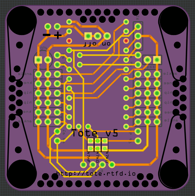
    I've been asked for a Tote kit for a Christmas preset by a friend, and I realized I no longer have any version 4 boards. So I had to go and order some. But if I'm ordering boards anyways, why not make some improvements here and there? So here's a version 5.

    You can see the board is much simpler now. It's basically just the servos, the battery, the pro mini, power switch and ir sensor. There are still the optional battery monitoring, piezo, distance sensor and extra capacitor, but by default they are not used. I also switched some pins around, so now using the serial pins for servos -- but all the analog pins are free, and broken out close to each of the legs. That should make it easier to use them for sensors.

    There is also a new step-by-step assembly tutorial for this version at http://tote.readthedocs.io/en/latest/assembly_v5.html and slightly modified code at https://bitbucket.org/thesheep/tote/src/tip/v5.

    And I still have the other 9 boards to give away.

    Oh, right and a DirtyPCB link: http://dirtypcbs.com/store/user/preview/1154

  • Pimp Your Robot II

    deʃhipu11/10/2016 at 11:09 1 comment

    So, today I hotglued the lenses with the LEDs, updated the software to let me switch the LEDs on and off, added a piezo to the robot, so it makes sounds, and painted some red highlights on the legs. The end result:

    And here's a short video:

  • Pimp Your Bot

    deʃhipu11/09/2016 at 21:30 0 comments

    The winter is coming, and my robots need some maintenance -- after a year of traveling to various conferences and fairs, they accumulated a number of injuries. It's also a good idea to recharge the lipo batteries once in a while.

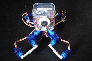
    I started repairing the robots, replacing broken servos, tuning them, etc. -- and at some point I realized that they actually look pretty drab. Just a bunch of wires and servos, really. Of course, the idea was to make them as simple and easy to make as possible, so that's just expected, but still they don't look like something you would actually want to have. That's when I decided to take one of the prototypes (incidentally, the one that I used for proprioception experiments), and make a chassis for it, to make it look a little bit better.

    So I went to the Internets and started to look through concept art of various robots. I'm quite surprised and saddened by how many of those are simply "a human in suit with a weird helmet". Oh well. Finally, I found one drawn by Paul Denton that fits Tote well and should be simple enough to make:

    It's a bit dark and gritty, but that's even better -- any mistakes I make will not be as visible. So I started with a plastic box -- from a set of toy blocks for kids. Of course I started by cutting the corners:

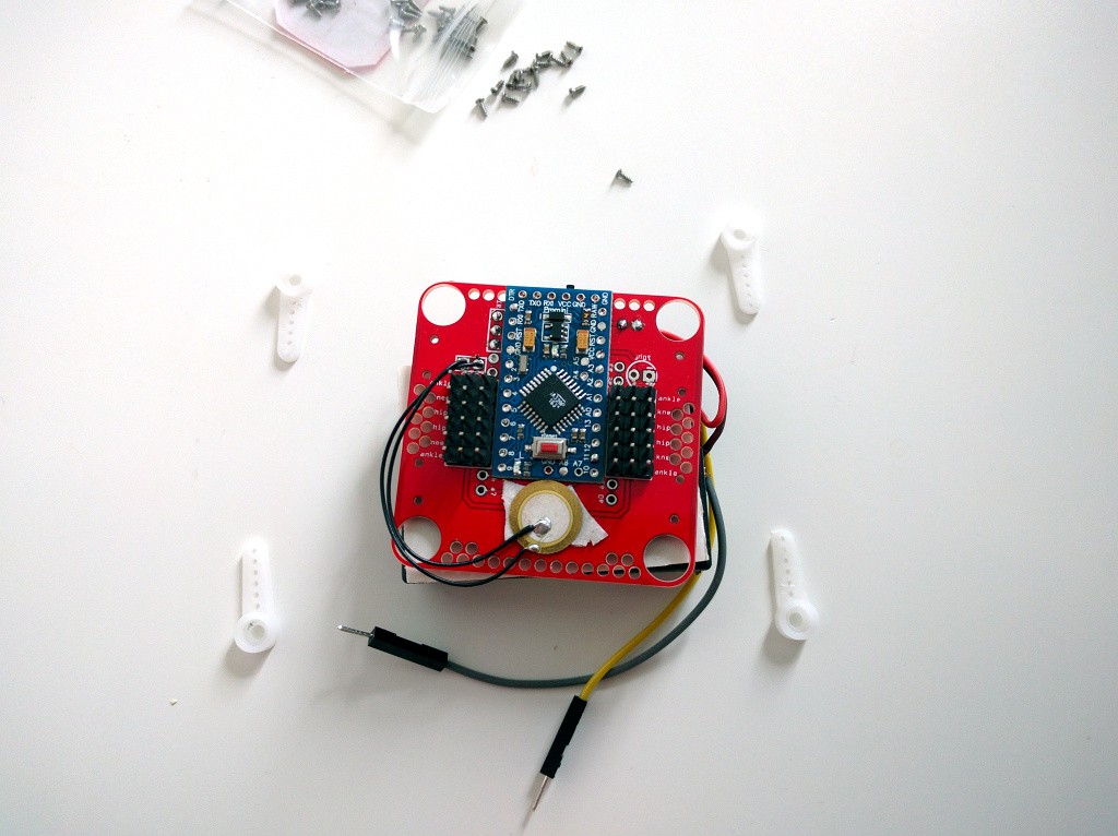
    Then I removed the legs from the robot, and installed the PCB inside the box:
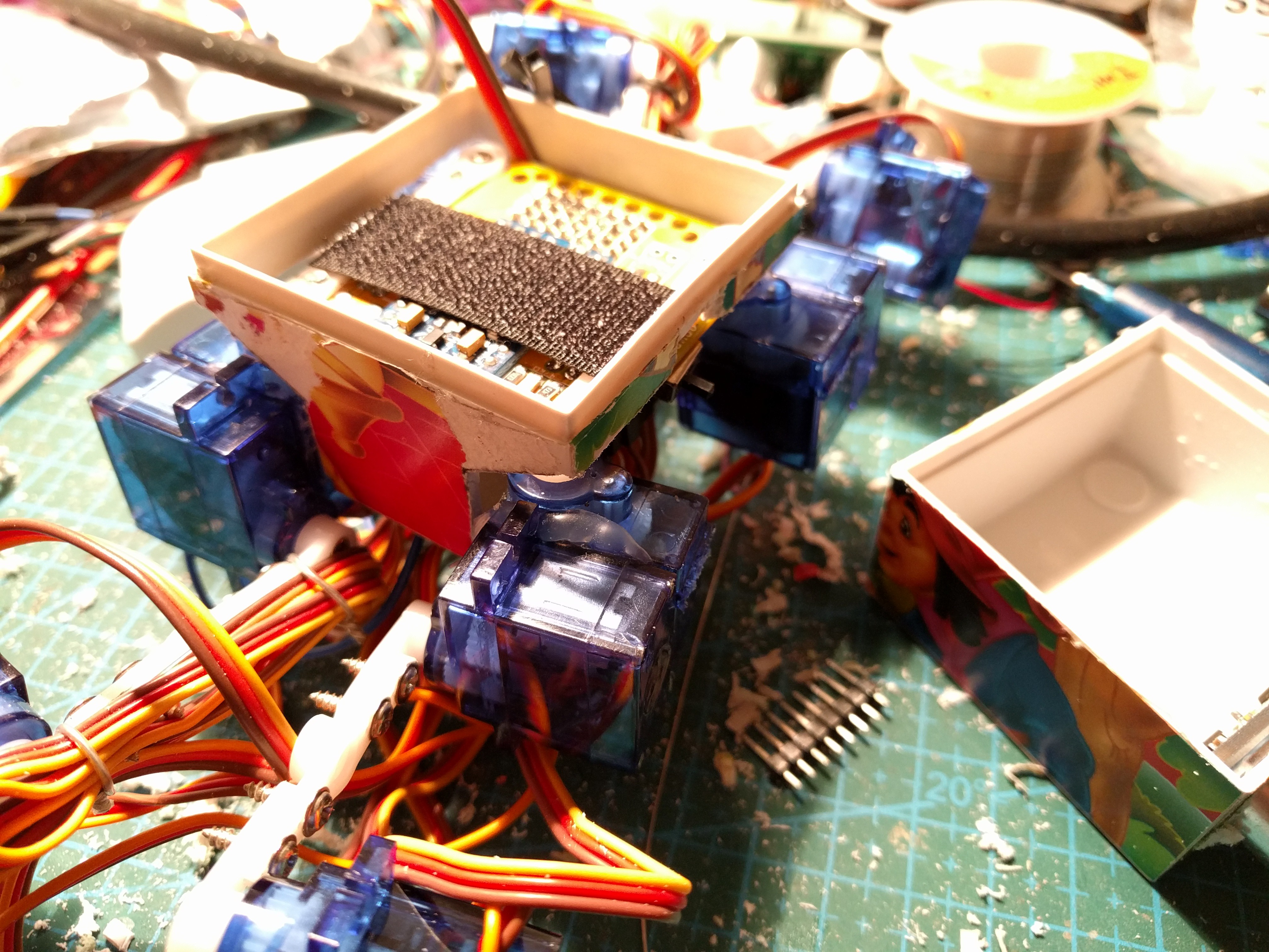
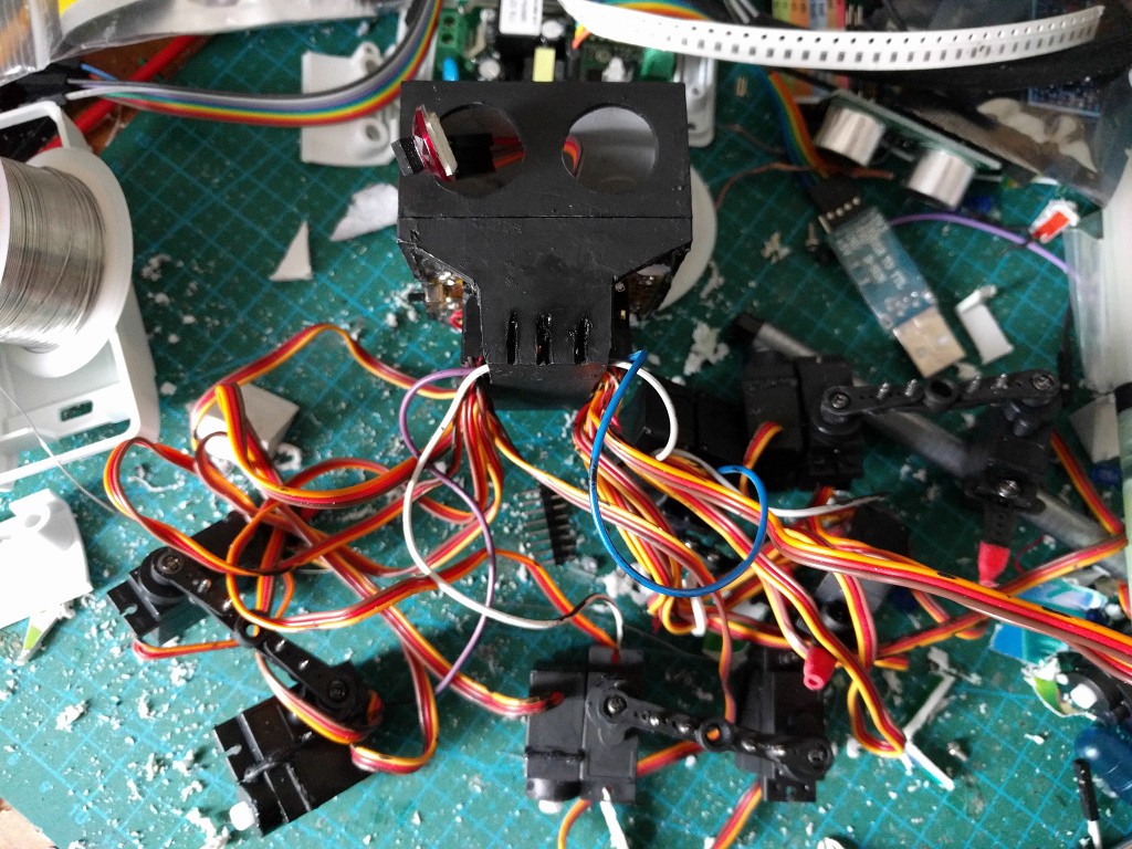
    I had to cur the sides of the box, and also the "ears" on the servos -- to make them fit properly without colliding with the box or with themselves. Once I was happy with the shape, I hot-glued the PCB securely in place and started painting. I'm using acrylic paints for painting tabletop battle miniatures. It sticks pretty well to plastic.

    Once I had the base coat ready and it all dried, I started to dry-brush some of the wear and old paint on it, then dry-brushed the whole thing with metallic paint, to make it look like beaten metal.
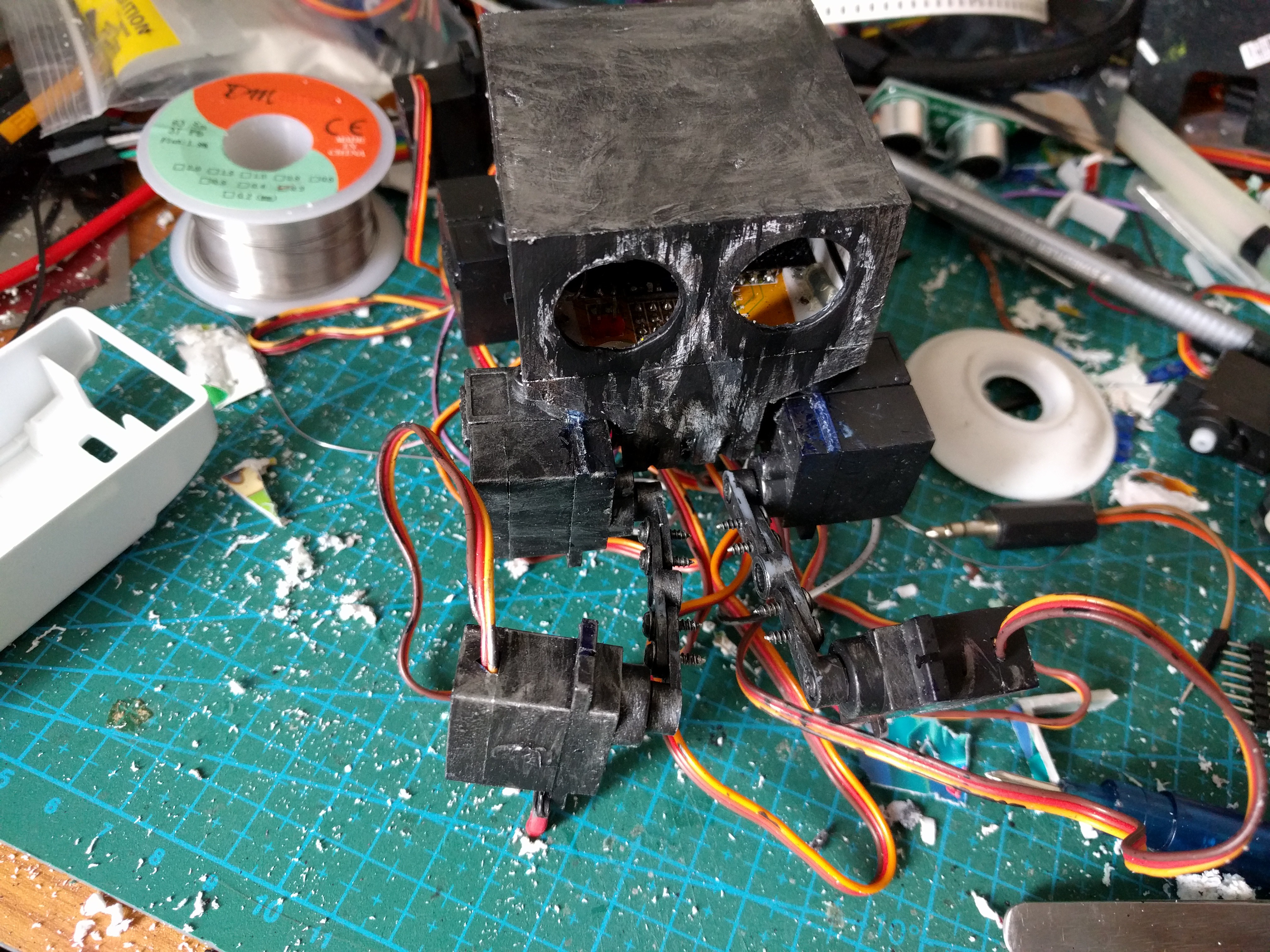
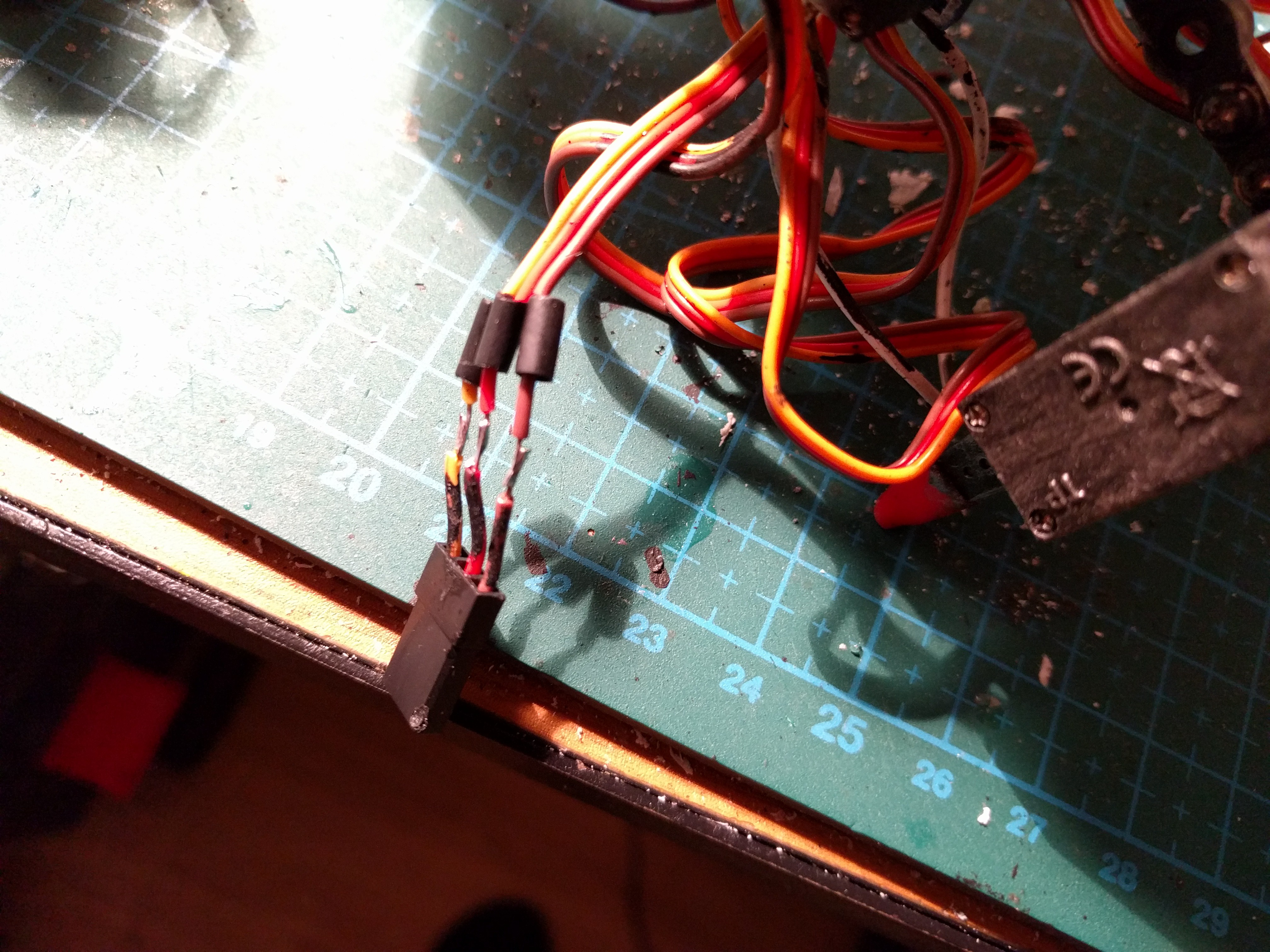
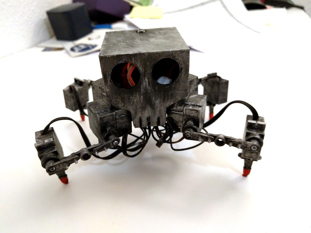
    Next, I had to do something with the wires. They are way too long, there is not enough space inside to hide them, and they are the wrong color. After some deliberation, I decided to just cut them to size:

    And then I also painted them black. Some mor dry-brushing, and it's almost ready. I also made a hole at the top for the IR sensor for the remote to stick out.

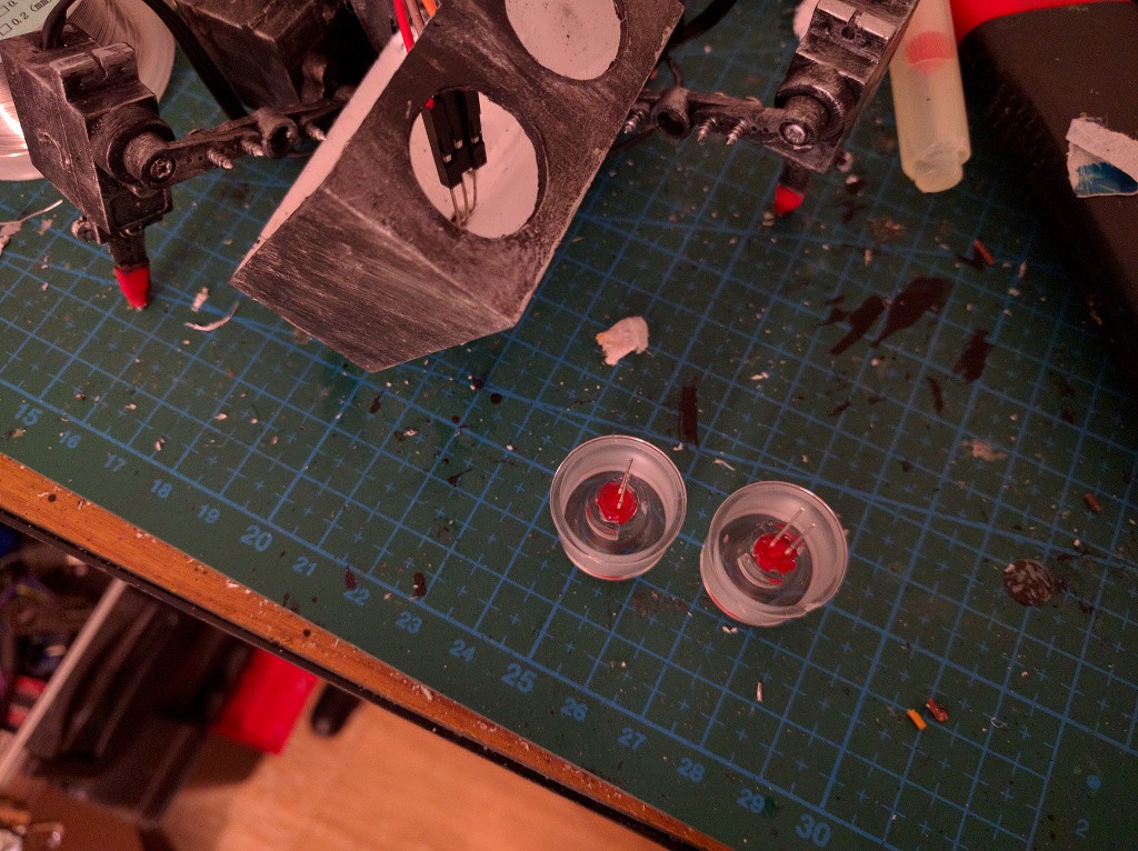
    Next, I worked on the eyes. I found some plastic lenses for LEDs in my drawer, and some red LEDs:

    A bit of glue to secure the LEDs in place, some more to glue the lenses into the eyes, and some resistors and wires, and it's almost ready. Now I just need to wait for the glue to set...

View all 48 project logs

View all instructions

Enjoy this project?

Share

Discussions

tsmspace wrote 01/06/2017 at 17:58 point

i am responding about the comment below/above regarding an extra leg servo, and then an extra foot servo. Im sure the price is astounding, meaning the hobbyist cant possibly afford it yet, but rather than a foot servo, i was thinking just last night that the fiber that contracts like muscles might be a good foot addition. Rather than rotation, it would work like a spring, it could possibly bring easier jumping to spider shaped robots by giving them a sort of heel. The leg would bend away from the body towards the end of the foot, and would pull in two directions, in and out. This might also help stabilize the foot when trying to manipulate objects, and also might improve climbing stability. As i said, though, i doubt they are anywhere near the cost of a hobby servo , being relatively new and (guessing) probably still intillectual property. 

  Are you sure? yes | no

deʃhipu wrote 01/06/2017 at 18:22 point

You can actually buy Nitinol wire today, and it's not prohibitely expensive (still more expensive than simple hobby servos). The problem is with driving it -- to make it change shape you have to heat it, usually by putting current through it. That's a lot of current, and it will only move as fast as you can heat/cool it (cooling is actually the harder part). It definitely won't work fast enough to allow jumping.

  Are you sure? yes | no

ActualDragon wrote 12/21/2016 at 16:28 point

note to self, use micro servos next time XD

  Are you sure? yes | no

ActualDragon wrote 11/09/2016 at 22:06 point

why is this on pi projects

  Are you sure? yes | no

deʃhipu wrote 11/09/2016 at 22:20 point

  Are you sure? yes | no

George I Fomitchev wrote 08/15/2016 at 06:58 point

if you need parts from a plywood (we will be happy to make a free laser cutting)

  Are you sure? yes | no

tyspa wrote 06/21/2016 at 20:59 point

How well do the SG90 servos work at 3.2v? Everywhere I read it says minimum voltage 4.8. Do you have to recharge the battery well before it goes dead?

  Are you sure? yes | no

deʃhipu wrote 06/21/2016 at 21:42 point

If you look at https://hackaday.io/project/6050-tote/log/24644-weight-lifting you will see they work pretty well indeed. They are a little bit weaker than with 5V, but not greatly. I have no way to measure the actual toque, of course.

I make Tote shut down once the battery reaches around 3.6V for a longer time -- that's about 20 minutes of continuous walking in circles.

You can also improve the servo strength by feeding it higher frequency signal -- for instance 75Hz. Then the energy will be about the same as with 5V at 50Hz.

  Are you sure? yes | no

0xF wrote 02/21/2016 at 00:07 point

Hi, just dropped by to say I admire your work, and that I'm currently building a bot based on this basic architecture. cheers!!

  Are you sure? yes | no

deʃhipu wrote 02/21/2016 at 10:06 point

That is great news! I can't wait to see what you come up with. Don't hesitate to ask if you get stuck with anything!

  Are you sure? yes | no

JOhn gado wrote 02/06/2016 at 15:59 point

Hi :)

What do you think about this arduino pro mini which work with both 5v and 3.3v : http://www.ebay.com/itm/221030168024?_trksid=p2057872.m2749.l2649&ssPageName=STRK:MEBIDX:IT

I think it only work with 16Mhz.... Do you think it will be a problem  ?

Thanks for your project ;)

  Are you sure? yes | no

deʃhipu wrote 02/06/2016 at 16:15 point

Hard to say, I never had an "adjustable" pro mini. Usually the difference is only in the voltage regulator and fuse configuration -- 3.3V pro minis have a 3.3V regulator and the fuses set to 8Mhz, 5V ones have 5V regulator and 16Mhz fuses. While you can easily use an ISP programmer to change the fuses, not sure how you would "adjust" the regulator (Perhaps there is some jumper in there that you would cut? I have no idea.)

  Are you sure? yes | no

tyspa wrote 11/05/2015 at 21:54 point

Great project!

Where did you find those orange servos? The ones I find are all blue :)

  Are you sure? yes | no

deʃhipu wrote 11/05/2015 at 21:57 point

On AliExpress. They are called "mr rc".

  Are you sure? yes | no

ioddevs wrote 09/06/2015 at 06:13 point

Radomir, thanks for the awesome robot.

I was printing your PCBv2 from the link, and build two.

do you have idea why after a few seconds walk, it straighten up its leg and lock there?

have to reset which just repeats the same thing basically.

The other one, seems to have cyclic reset. i noticed the blinking led and the leg init.

please teach me.

thanks.. awesome robot

  Are you sure? yes | no

deʃhipu wrote 09/06/2015 at 08:51 point

This is most likely the low battery shutdown. If you didn't include the battery voltage monitoring circuit (the two resistors and a capacitor), or there is a bad connection in it somehow, the robot will think that the battery is low and will shut down to protect it. You can work around that by commenting out the "battery_loop()" line from "start.ino".

  Are you sure? yes | no

Over.Unity wrote 08/29/2015 at 12:53 point

Hi Radomir,

Thanks to your excelletn guide I have completed one of these robots, please find the info for my build here

https://hackaday.io/project/7473-tote-in-the-wild

I would thoroughly recommend anyone looking to build their first (or subsequent) walking robot give this a go, it works just as the documentation states and is very cost effective.  Thanks for all your hard work.

  Are you sure? yes | no

deʃhipu wrote 08/29/2015 at 12:59 point

Thank you!

  Are you sure? yes | no

Alvaro Barcellos wrote 07/09/2015 at 21:14 point

For each leg you have a body, thigh and calf servos, If you put a extra servo between the body and thigh , you can make any leg act as an arm too.  ( |/\  to |_/\ ).  mind it ?

  Are you sure? yes | no

deʃhipu wrote 07/10/2015 at 05:58 point

Thanks for the suggestion, but It's not that easy.

First of all, since the robot only has four legs, and it needs at least 3 legs to stand, I can use at most one leg at a time for a "hand". That means that without installing a gripper at the end I can't really grab anything. Thinking about it now, I could probably add small fixed legs under the robot's body, so that it can "sit" on the ground first, and then use all 4 of its legs freely. I might try that.

Second, I can already reach any point in range of the leg without the extra servo, so I can use the legs for manipulating objects already. I'm afraid that the extra servo would add to mass and price of the robot and complicate the inverse kinematics calculation without actually giving me much more range or degrees of freedom. Adding a servo at the end of the leg would make more sense, since then I could have flat feet (I would have control over the foot's angle), and maybe even a gripper, but I want to keep this stuff simple mechanically.

I will have to try object manipulation, similar to what this robot does at 1:15:

Thank you for the idea.

  Are you sure? yes | no

Alvaro Barcellos wrote 07/10/2015 at 14:57 point

You are correct about equilibrium and extras parts, and if can reach any point, really you just need one up/down tail at middle of body to use two legs as arms and grab or touch things small. thank you for reply. 

  Are you sure? yes | no

deʃhipu wrote 07/10/2015 at 15:16 point

Yeah, an additional leg would work, but that means I would need to control an extra servo, and the Arduino Servo library can only control 12 on the Pro Mini. So I would need to either write my own or change the microcontroller board, and that again raises costs.

Short fixed legs (or just a carapace at the bottom) would actually be sufficient. Right now the robot can't "sit" on the ground and move its legs, because the bottom-most parts are the leg servos, which need to move. If I added some battery compartment at the bottom, or some fixed legs, sticking just beyond the leg servos... Sorry, just thinking aloud. You really got me thinking about this, thanks.

  Are you sure? yes | no

Alvaro Barcellos wrote 07/10/2015 at 15:28 point

you are welcome to thinking.  Well, 1 timer, 4 lines, 2 x 74hc4017 may could control 20 slow servos alike. and invert that body ones left bottom free. sorry, idem. thanks

  Are you sure? yes | no

H wrote 06/28/2015 at 23:48 point

If you make the legs shorter is it less twitchy but walks slower? Also what do you think of mounting little motorized wheels to the bottom of the body for driving on flat surfaces, or maybe even two rotors to make it fly (the rotor motors would be fixed to the body and the legs would move to balance)? Just throwing ideas around.

  Are you sure? yes | no

deʃhipu wrote 06/29/2015 at 07:23 point

Yes, there is a trade-off in the length of the legs. Longer legs have better range, move faster and let you make longer steps, shorter legs are more rigid, stronger and have more precision. It's also important which segment of the leg you are changing, for instance, elongating the coxas gives you longer steps, but doesn't constrain the overall weight of the robot, as that part moves in the horizontal plane and so doesn't have to lift the robot's body. Before Tote I made several prototypes and experimented with different configurations, and this is what seems to be the best compromise.

I will probably have a log at some point about changing the dimensions of the robot and the effects it has on its movement, thank you for suggestion.

About adding wheels and propellers -- sure, that's possible, you are effectively just strapping another vehicle to it. You just need to figure out how to communicate between the two (or more?) parts, and of course there are severe weight and battery power constraints, but in principle such hybrids are possible. Personally, I want to focus on the robot itself and its walking, and leave experiments with various appendages and attachments to others.

Having said that, I do have a proof of concept for a Logicoma-like configuration, that I want to try some day as a separate project: http://paste.sheep.art.pl/83219196-49f8-4a17-9bd2-974d6691346c/+inline

  Are you sure? yes | no

H wrote 06/30/2015 at 05:21 point

Thanks for the response, glad to know a fair bit of thought went into the leg lengths. I myself am too novice to try combining vehicles yet so I'll see how far I get on Tote since it looks like like the cheapest and easiest quad of all the ones I've looked at.

The logicoma looks cool, the best tachicoma I've seen is still this insane lego one which only uses 3 motors

  Are you sure? yes | no

davedarko wrote 06/04/2015 at 18:36 point

Are you aware that you are featured on the blog? Congratulations are in order, I guess :) http://hackaday.com/2015/06/03/hackaday-prize-entry-solving-the-shortage-of-walking-robots

  Are you sure? yes | no

deʃhipu wrote 06/04/2015 at 19:53 point

Thank you. That was a little bit unexpected, I was hoping it would happen a little further down the road, when I have more stuff posted. Fortunately I had one update almost ready, so I quickly finished and posted it, so that people can actually see something.

  Are you sure? yes | no

Neal D Corbett wrote 06/04/2015 at 11:40 point

That's a marvellous bit of work/documentation, thanks!

I was working on a similar quadruped a while ago, but I never got around to making it actually walk... (http://www.youtube.com/playlist?list=PLickeZlNSDh0KQy0r_vqYNvOmmn4DdvNf)

I'll have to try again after looking at your gaits-code :)

  Are you sure? yes | no

deʃhipu wrote 06/04/2015 at 11:46 point

This is really nice! I see you have the inverse kinematics worked out, so you are really close. Now you just basically need to make it move the legs backwards, and move them back forward one at a time when they reach their limit. The code I wrote is still a little ugly, but what you need is basically in this file: https://bitbucket.org/thesheep/tote/src/043ede638ace1396ca5df22528986f386453d47b/start/creep.ino

  Are you sure? yes | no

Francisco Dominguez wrote 06/04/2015 at 06:23 point

Great design! Congratulations!

You are invited to publish your robot at the Let's Make Robots site (http://ow.ly/NBhgm) with explanations, videos and pictures for free and you can:
1. get free robot kits and parts! ;-)
2. see your robot published around the World, here in this group, also in Twitter: http://twitter.com/LetsMakeRobots
3. Be part of the greatest community of robot makers in the World!
Enter here now and be a member (for free): http://ow.ly/NBiMC

  Are you sure? yes | no

deʃhipu wrote 06/04/2015 at 07:55 point

Thank you Francisco for the invitation. I'm already a member (for free) since over a year. I joined Let's Make Robots over a year ago, and had some great conversations in there and I have great respect for the community. However, after some unpleasant discussions on the forum, I decided it's not the right place for me and moved on. I can only be involved in so many communities at once. I still read the forums regularly and try to help, but I don't want to put my projects all over the Internet, in a web of outdated and obsolete pages (because I wouldn't have the time to update each of the projects on every website every time).

I think that Let's Make Robots is a great community and great place to get started with building robots, to get valuable information and even more valuable motivation. I refer people to it in all of my robot-related talks. I just personally choose to keep my project descriptions in one place, here.

  Are you sure? yes | no

Similar Projects

Does this project spark your interest?

Become a member to follow this project and never miss any updates