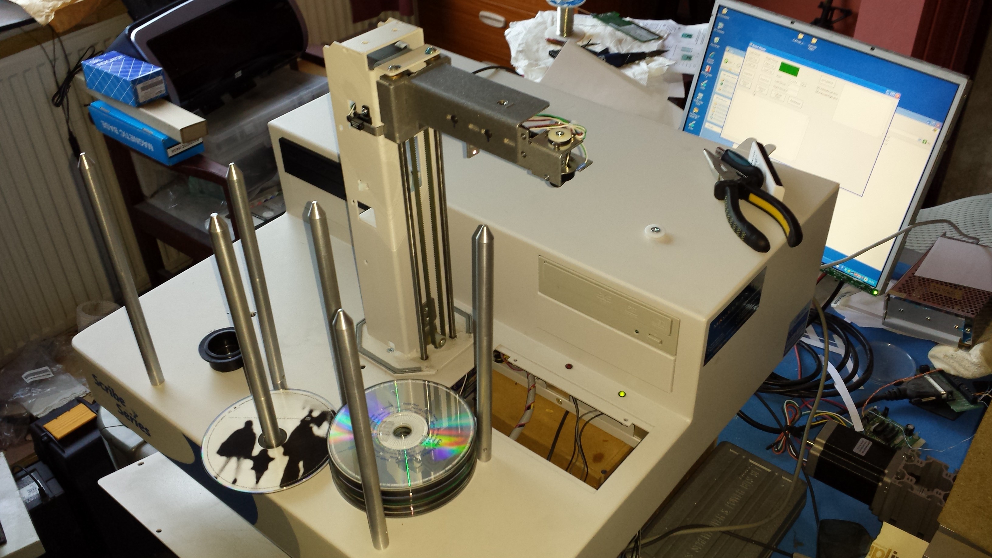
So here's the whole shebang, with my software running on the screen. Because it's still very much WiP, it's in pieces. The rotator arm should normally have a hexagonal metal shell, and the vertical arm should normally have a metal shell too, off for maintenance purposes.
You can also see that the front part is missing an underside, the machine body is actually up on a box here (the brown thing visible thru the rectangular hole at the front), with the front underside (with driver board) sitting on the table, this helps diagnose it, so if the robot has an epileptic fit or something, I can simply wrench the power out of the driver board.
Speaking of -

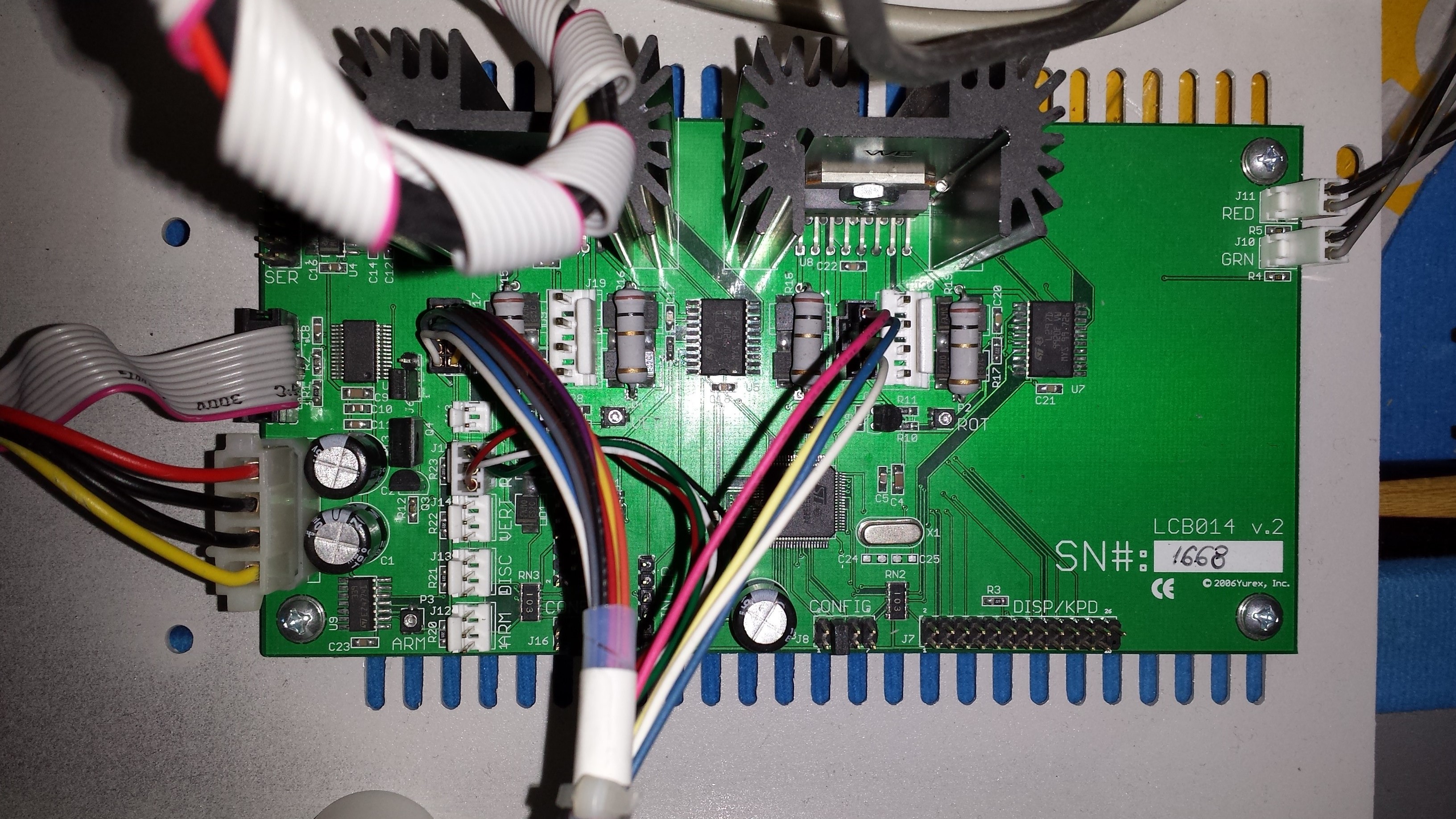
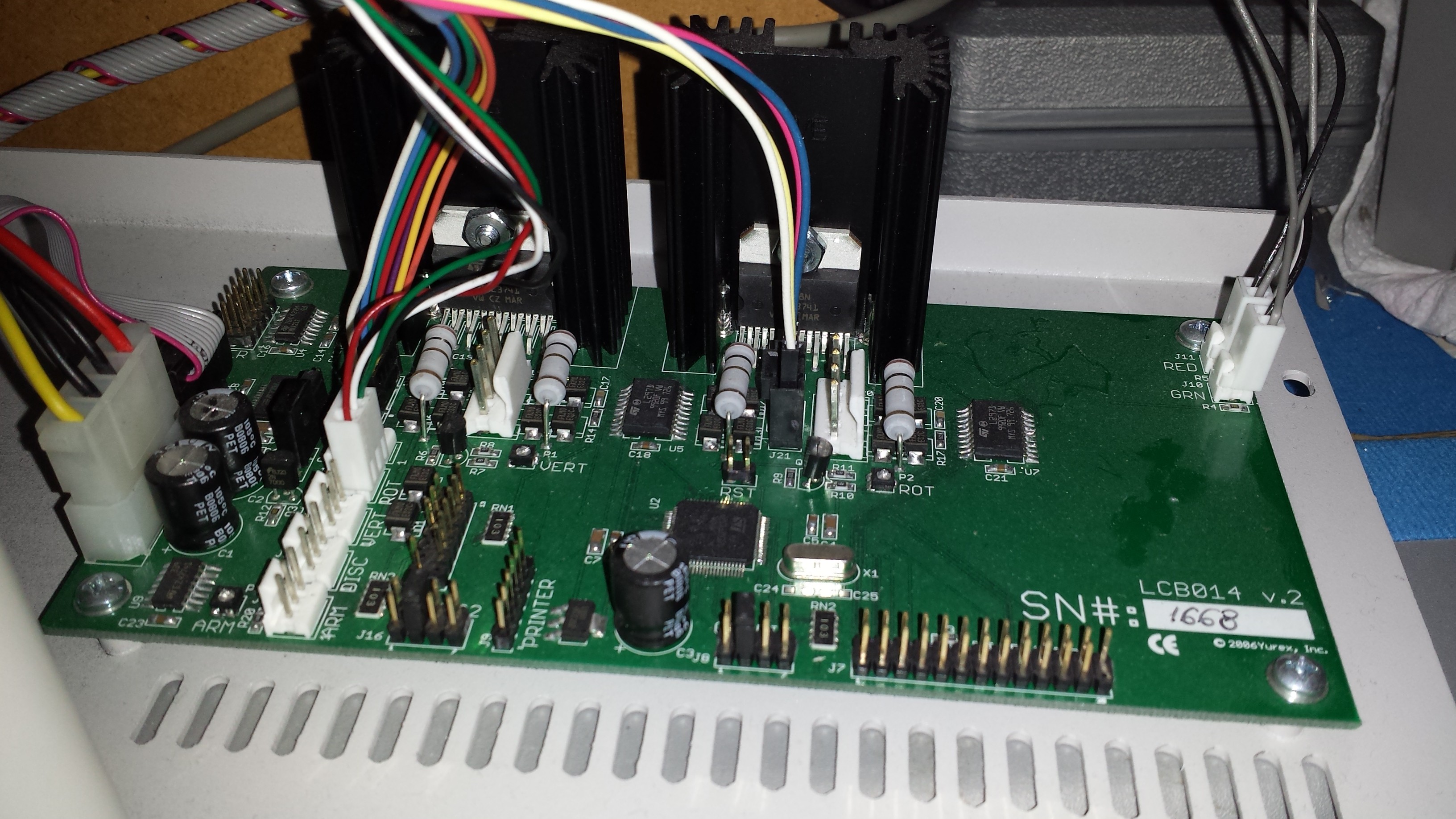
This is the LCB014 v.2 driver board built by Yurex Inc. from New York. There's precious little details about this board though online. Any more info anybody knows would be appreciated, as I think I'm missing some features it can do, such as 'disk shake' to ensure the disk is seated correctly on a drive tray.
Along the top you can see the stepper driver chips and massive heatsinks, one needed for each stepper driver, although I'm sure a high-ish current would also be required for the gripper solenoid, so that's in there too somewhere.
I'm guessing the SMD chips and associated stuffs just below the stepper drivers are just encoders for the drive patterns for the steppers. Not sure.
The big square chip near the middle is the ST Microelectronics uC / ARM chip, which I believe is the whole reason it can listen on a serial connection (via USB) and perform the disk pickup and placement it does, which is pretty much just some rudimentary behaviour of just initiating motor drive (just linear) and reacting to sensors. Could probably really be done with a PIC16F... chip.

The wiring is luckily, really straightforward. There's a dedicated connector per stepper and sensor for rotation, another for vertical motion, and another for the gripper arm. On the left is the motherboard USB header connector, which goes back to the PC motherboard, not to a USB connector, and my old favourite, the standard Molex disk drive connector of yore!
Interestingly there are extra unused connections for ARM, DISC, VERT and ROT, where ROT is the only one in use. There are very interesting looking connections along the bottom, labelled CONFIG and DISP/KBD. assumably for a screen and controls.
Lastly on the right are RED and GRN connectors, for the indicator LEDs. In normal operation green is permanently on, whereas RED comes on when there's any 'error condition', such as if the disk was dropped.
Discussions
Become a Hackaday.io Member
Create an account to leave a comment. Already have an account? Log In.