The Muffsy Phono Preamp PP-3 has been redesigned from scratch. There were a few design elements that were deemed important:
- Size: Standard width of 84 mm (same as the power supply)
- Screw terminals: Must fit within the PCB, and not cover the text
- Audio paths: Shorter and equal length
- Input capacitors on the PCB
- Gain: Both switches set to "OFF" must have a function
- Even better power filtering
- Space for larger audiophile resistors in the audio path
- Improved copper traces for variable size output capacitor
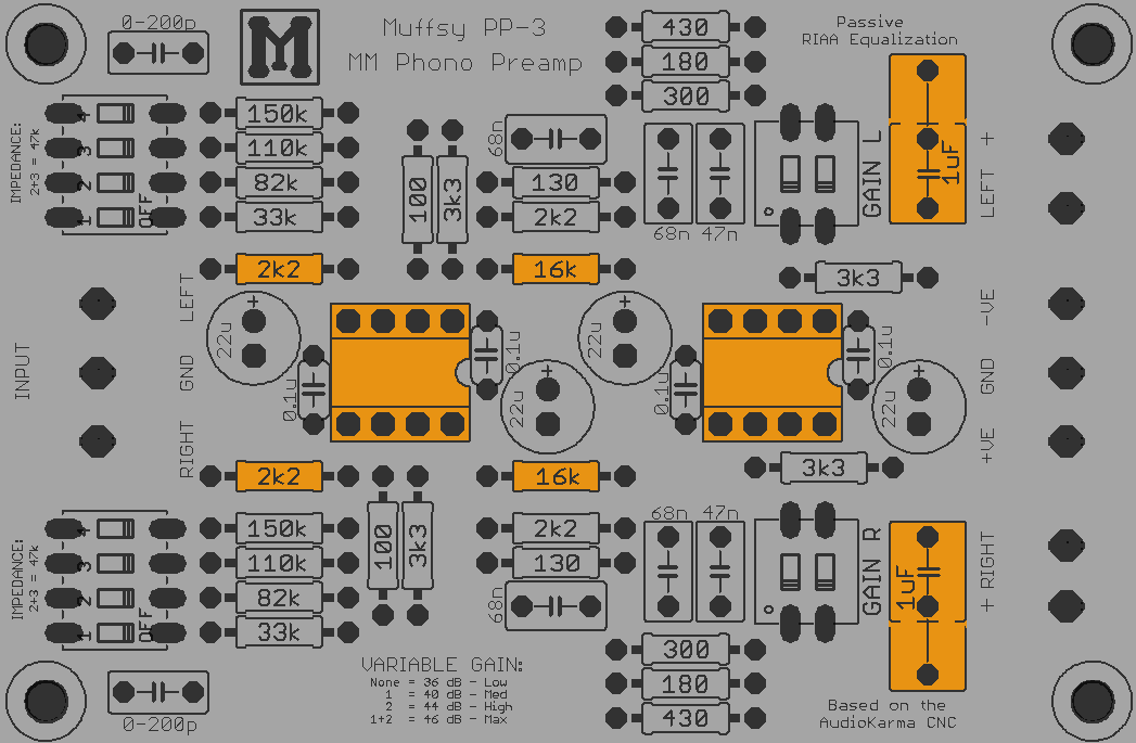
The picture above shows the top-side of the PCB, the components in the audio path are colored orange. Notice the extra space around the resistors that gives room for the larger audiophile type resistors.
Size
The size of the board is now 84x56 millimeters. This is a standard PCB width, and will make it easier to install in a variety of enclosures.
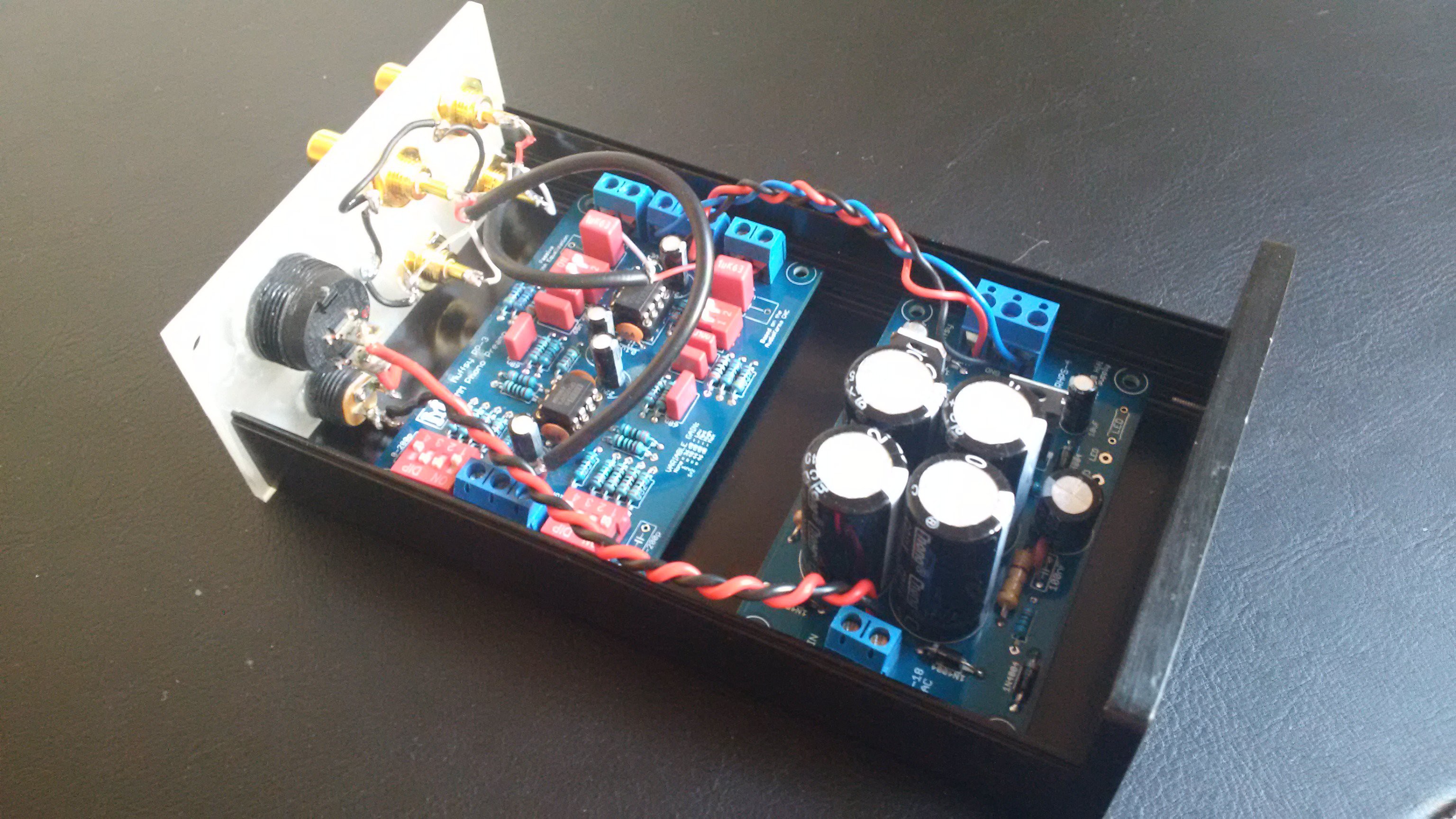
This PCB (and the power supply) will slide into the grooves of a B-0905 enclosure, as you can see in this picture:
Screw Terminals
Screw terminals now fit nicely on the board, with space left over on the outside. This can also be seen in the picture above.
Audio Paths
Because of the shorter length of the board, and the added space for screw terminals, the audio paths are abysmally small. What's more, the left and right channel audio paths are exactly the same length.
Input Capacitors
The input capacitors are back on-board. Check this project log for more information.
Gain
Another gain level was added, with both switches set to the "OFF" position. Check this project log for more information and how to modify the gain to suit your requirements.
Power Filtering
The electrolytic bypass capacitors are now 22 uF, up from 10, which will filter the power even more. The 10 uF capacitors will still fit though.
Resistors in the Audio Path
Notice that the two 2k2 and the two 16k resistors in the audio path has more space around them. That will allow the use of Vishay Dale or similar type of larger resistors. All other resistors are not in the audio path, so they won't contribute to the sound signature.
Improved Copper Traces
All traces have been shortened considerably, and both audio channels are exactly the same length. The two channels are also highly symmetrical, apart from the two gain resistors in the first gain stage.
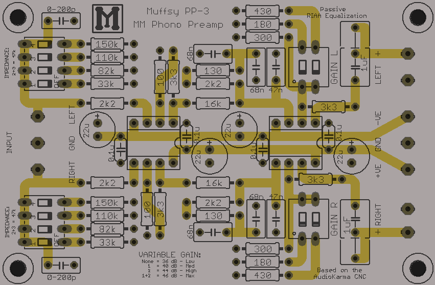
The copper traces for the output capacitors has been re-routed to improve the connection of larger sized capacitors.
Two of the key elements to doing this was rotating the input impedance switches and changing the placement of the RIAA equalization circuit components.
Discussions
Become a Hackaday.io Member
Create an account to leave a comment. Already have an account? Log In.