 Hayden Kroepfl
Well now I'm feeling a little silly, the issue turned out to entirely be that I was flashing my Flash chips backwards. The tool I was using to output my byte code produces two bin files, name_0.bin and name_1.bin, for some reason I assumed that 0 would be the low bytes, and 1 the highs. However if you look in the program it does show that the even (low) bytes are in 1. Now with that sorted it worked! It finally worked! Though not before I had completely rewired the computer and added a proper reset circuit (based off this document the only changes made were that I used 470k resistors as I didn't have 1Meg handy, this gives a reset of 270ms which is still enough) .
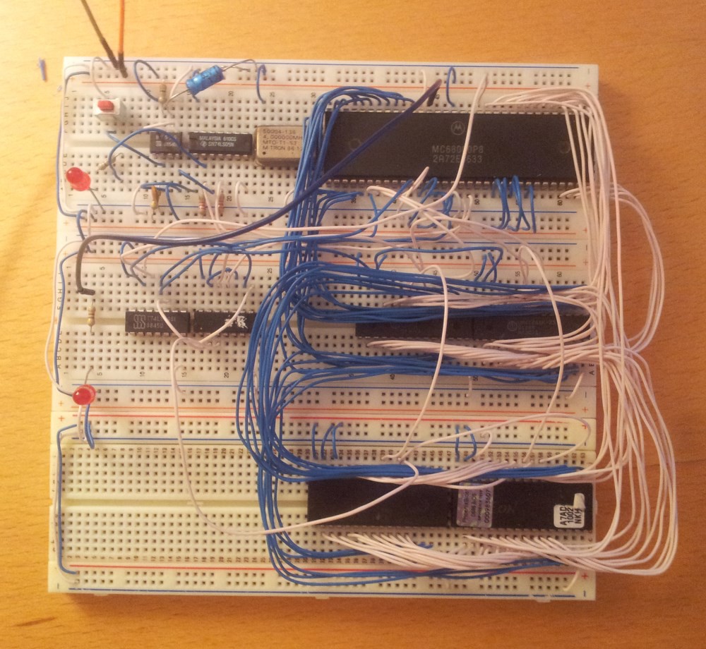
The new computer:
And here's the circuit behaving as expected, top line is the chip select from the RAM, indicating that A18 is set which happens during the write to memory, middle line is the chip select for the ROM, finally the bottom is the output on the led. This picture was taken while the LED was on, the pulse on the bottom line appears when the LED is on, and doesn't appear when it's off. It's not a very precise output but it's enough to show that the code and processor are working. Video of it working to come tomorrow, (potentially with my Arduino acting as a parallel to serial converter to print a Hello World message)
Discussions
Become a Hackaday.io Member
Create an account to leave a comment. Already have an account? Log In.