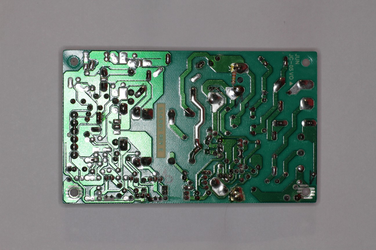
Posting up my latest schematic here, layout is underway but I would like some feedback if anybody has any? Just got initial word I may have an additional programmer to help out when the hardware is done. We have me on hardware/software, looks like I got another programmer today, and have a physical case being created too!

 sako0938
Discussions
Become a Hackaday.io Member
Create an account to leave a comment. Already have an account? Log In.
Thanks for your feedback on this! I asked another EE friend of mine and he agreed with you. That removes over $10 from my BOM, while making the PCB just a bit larger. Though still 4 traces will slightly be crossing the AC/DC barrier to turn on the relays.
Are you sure? yes | no
Because if I could get rid of the opto-isolater, I'd save in ~$10 in parts, because I can get rid of the isolated switching DC/DC regulator, optoisolator, and related components.
Are you sure? yes | no
I was thinking next version would have triacs, as I found them a bit confusing. The PCB layout that is posted currently is old, and I agree its a disaster waiting to happen, as its a proof of concept. However I am using the relay JS1-5V-F manufacturers part #. And in the datasheet now I see the breakdown voltage from the coil and the contacts is 1500VRMS for 1 minute, and apparently I can buy a 6kV surge current version of this relay too. Is that enough, as long as I route the PCB in a way to minimize creepage?
Are you sure? yes | no
Your PCB layout should have a clearly defined "hot side" and "cold side", with a sufficient creepage barrier between them where there are no PCB traces in the middle. The isolation components, such as the optocouplers and isolated AC/DC power module, should be laid out with their "hot side" and "cold side" on separate sides and they should be the only components that straddle the "firewall" gap.

You can see this sort of thing here, just as an example. But I can't really see the same sort of layout on your PCB, there seem to be traces going all over the place without tidy isolation between the hot side and the cold side.
Also, do you really need optocouplers *and* relays? Optocouplers are often used in mains AC switching applications where triacs are used, but if you've got a relay - and an appropriate relay has been chosen, with an appropriate PCB layout - then the relay itself can provide galvanic isolation up to 5kV, or whatever safety/engineering standard you wish to follow for the strength of the galvanic isolation. If the relay provides appropriate isolation, then the optocouplers are probably redundant.
Are you sure? yes | no