 Stefan Lochbrunner
Modification of the button board.
If there's something I dislike as much as hooking up a button with pull resistor, it's hooking up a LED. Yeah, I'm that lazy. Fortunately, the LEDs I have been using for quick tests didn't burn when I put 5V across them without current limiting resistors (they may or may not have turned from green to yellow though...).
Anyway, the other day I was thinking about putting together a new board but then I remembered the unused space/layer on the button w/ pull-up/down board. The reason why I wanted to combine the two is that when I order the PCBs and get ten panels I probably won't ever use ten buttons. This way I can at least use some of the boards for LEDs (and save the other LEDs from being tortured).
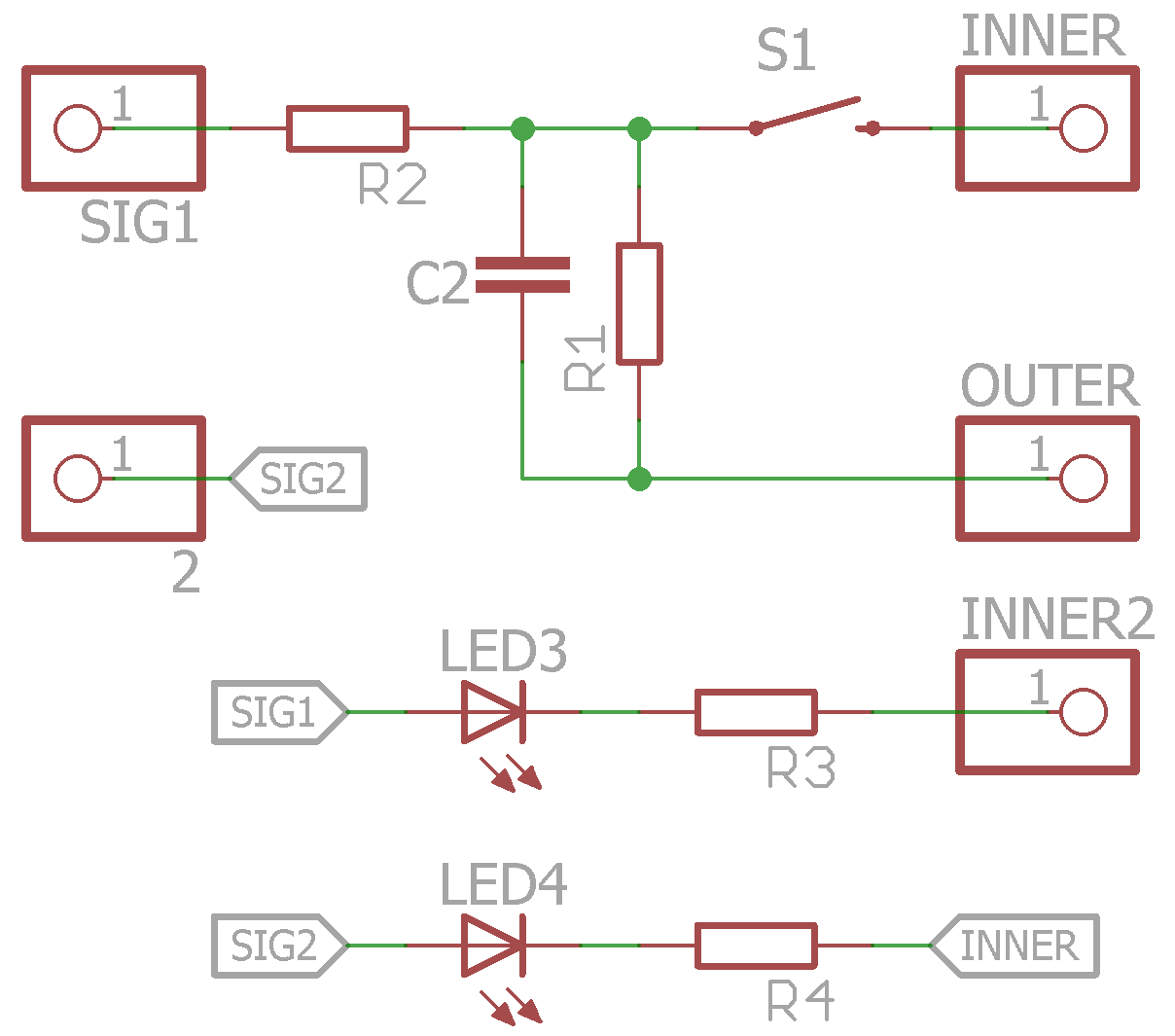
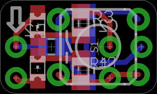
The way the button works is just like the previous version with the addition of an arrow indicating if the resistor pull is up or down. To make it a little more apparent how it works I've highlighted the pins that need to be populated for this mode:
The two pins on the right plug into the power rails and since they're staggered the board could also be used in the center of a breadboard. (Sorry for using these round pin header footprints that look just like the through holes of the tact switch but these fit best into the corners of the board)
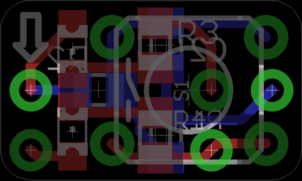
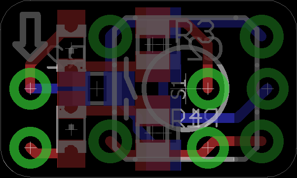
To use the board for LEDs, a different configuration of pins is required:
Update:
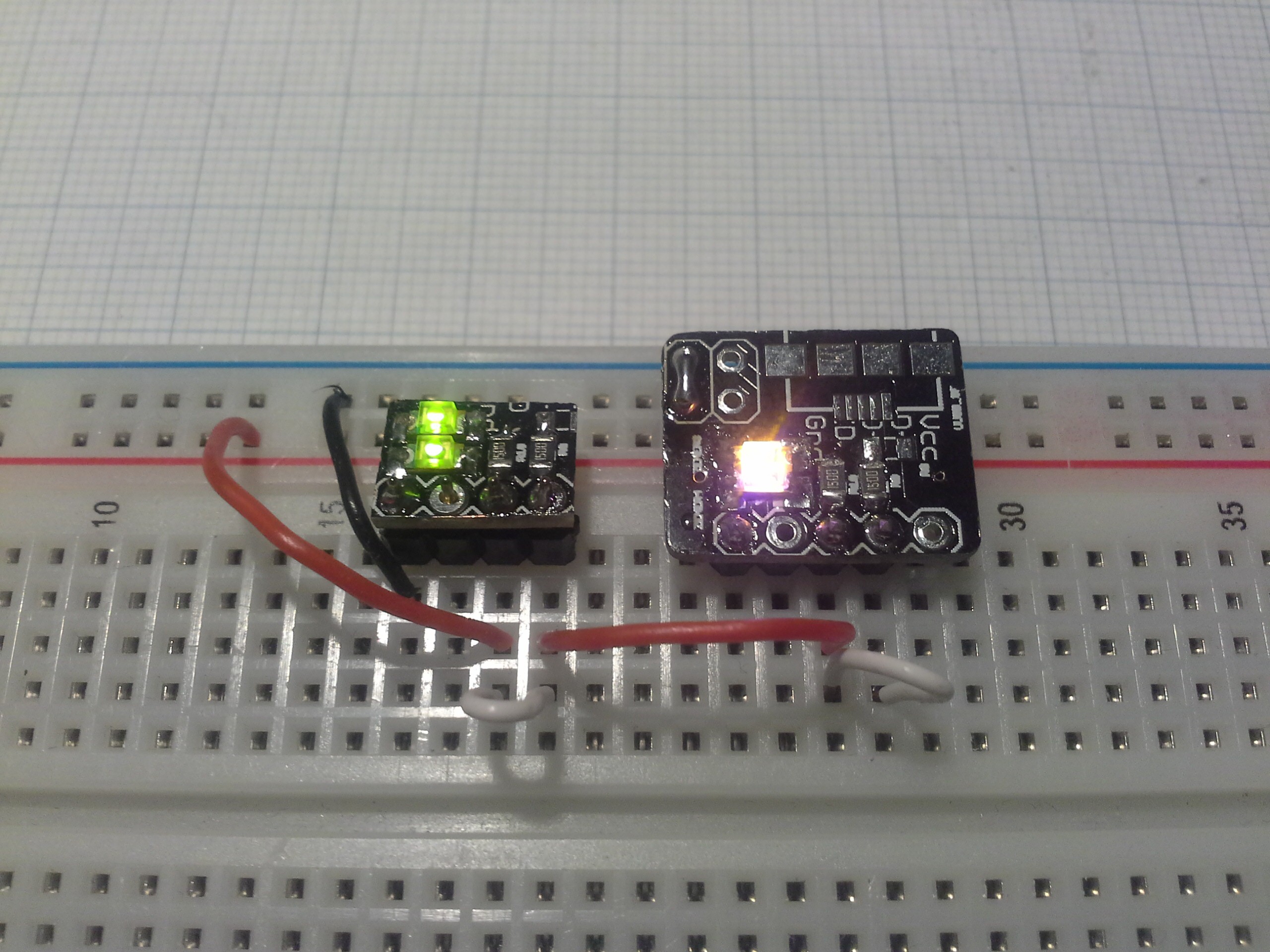
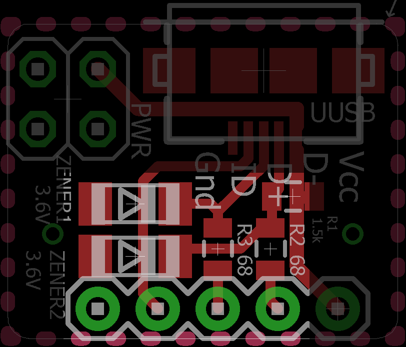
Here's just a quick hack on how to turn the µUSB Breakout into a breakout for SMD LEDs:
Update 2015-10-05
Here's just a quick demonstration of both modes of the board:

Discussions
Become a Hackaday.io Member
Create an account to leave a comment. Already have an account? Log In.