I haven't written about this one before because I think it's pretty trivial and self explanatory but for completeness here's the link to the GitHub repo. On a side note I'd like to mention that I chose the number of LEDs to be 5 because that's the max you can fit side-by-side in the rail of a breadboard but obviously you can just use another one of these to make up a whole byte.
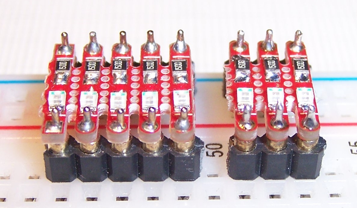
Another reason for this log is that I wanted to share some use cases for this board.
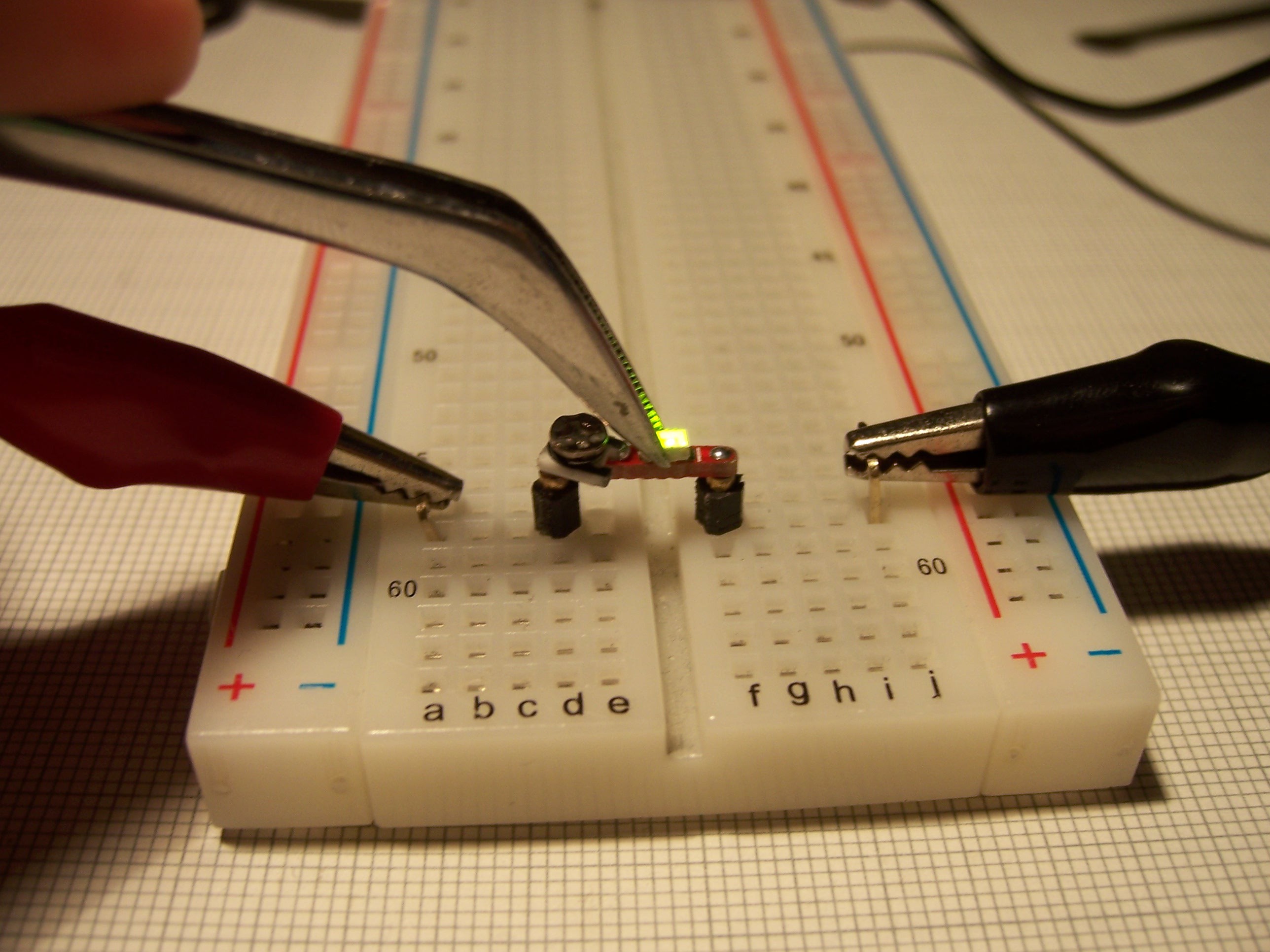
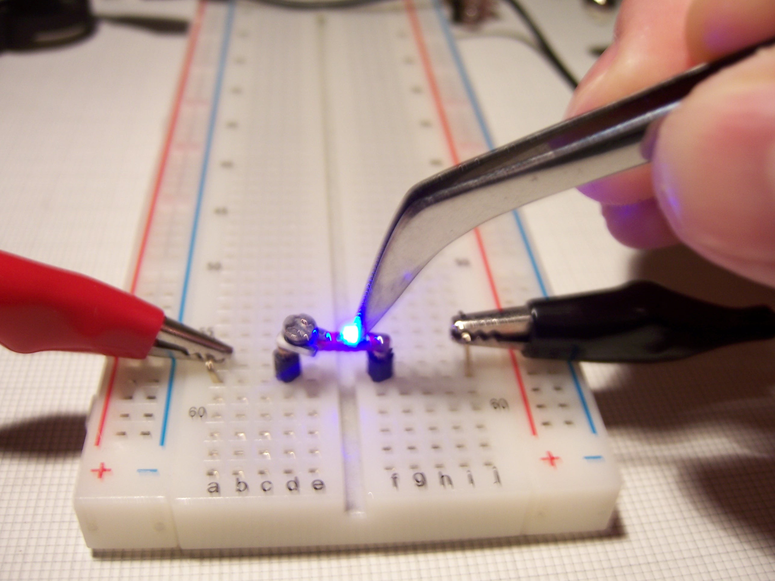
The first one is pretty obvious. Just don't solder the LED and you have yourself a SMD LED tester (optionally add a small potentiometer for good measure):

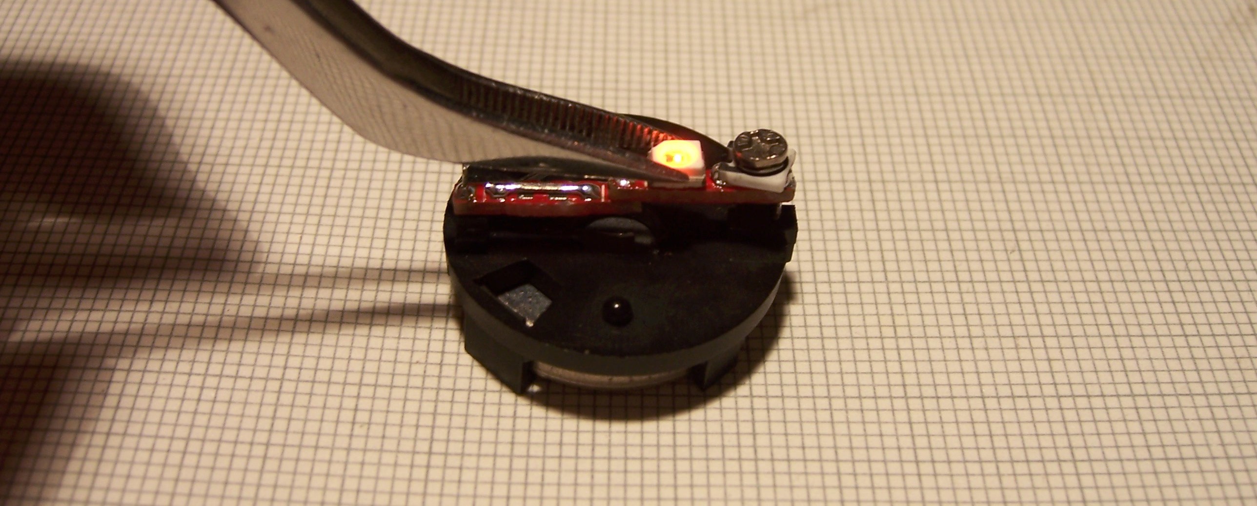 Just solder two of them to a CR2032 holder and that's pretty much it.
This next use case is for another project of mine where I tried to convert one of those cheap microscopes to be used for PCB inspection and maybe soldering:
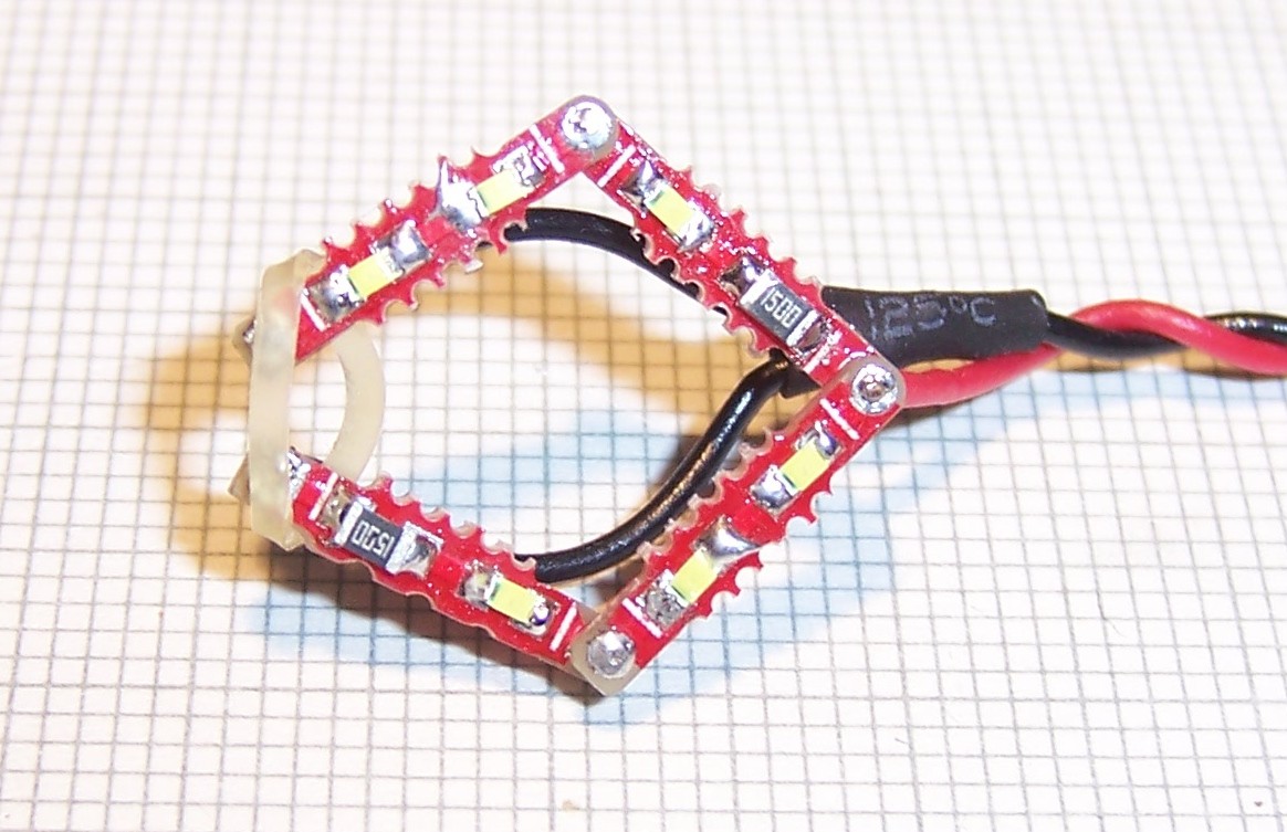
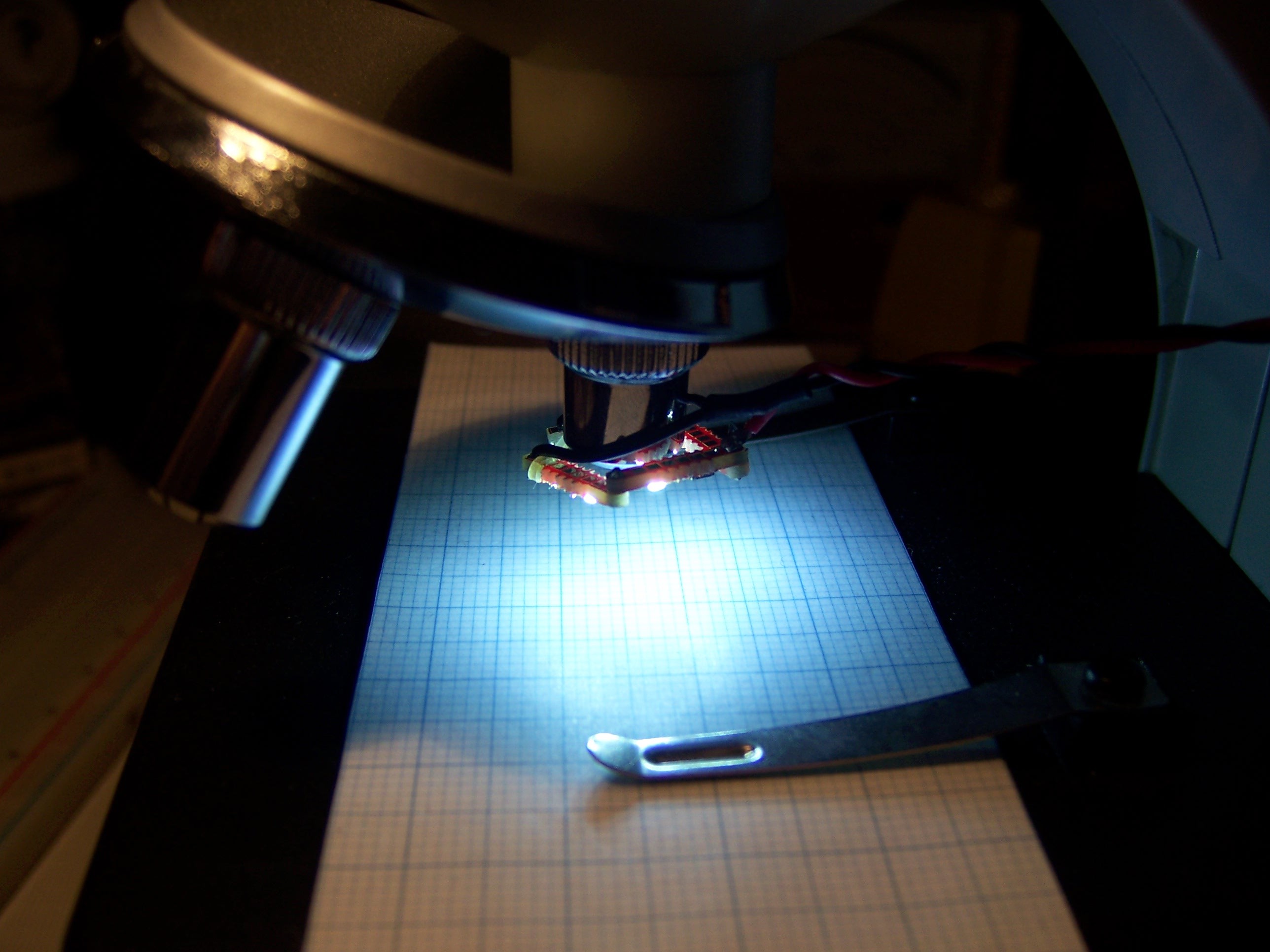
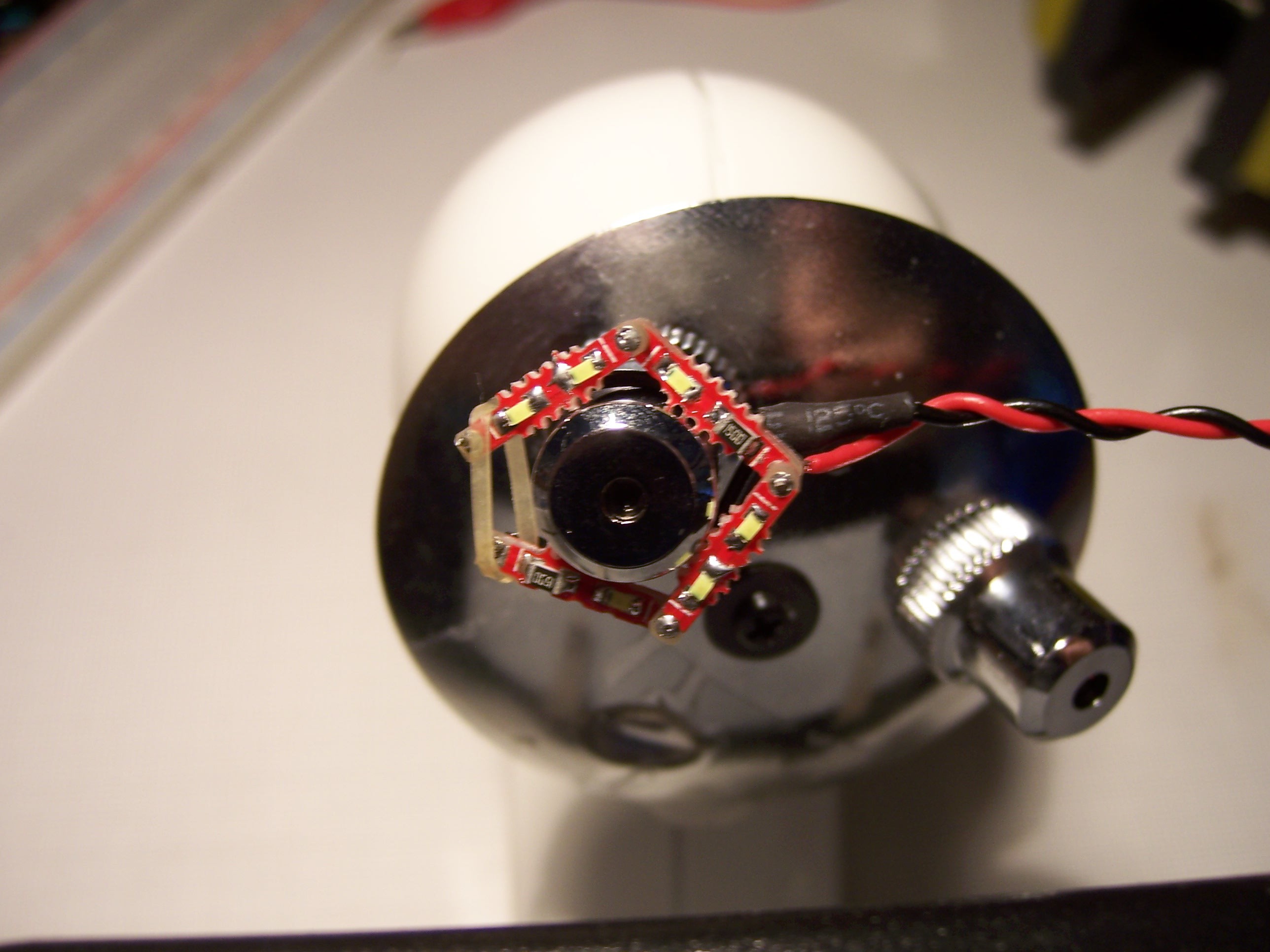
 Stefan Lochbrunner
Discussions
Become a Hackaday.io Member
Create an account to leave a comment. Already have an account? Log In.
Simple but awesome. Well done!
Are you sure? yes | no
Thanks!
Are you sure? yes | no