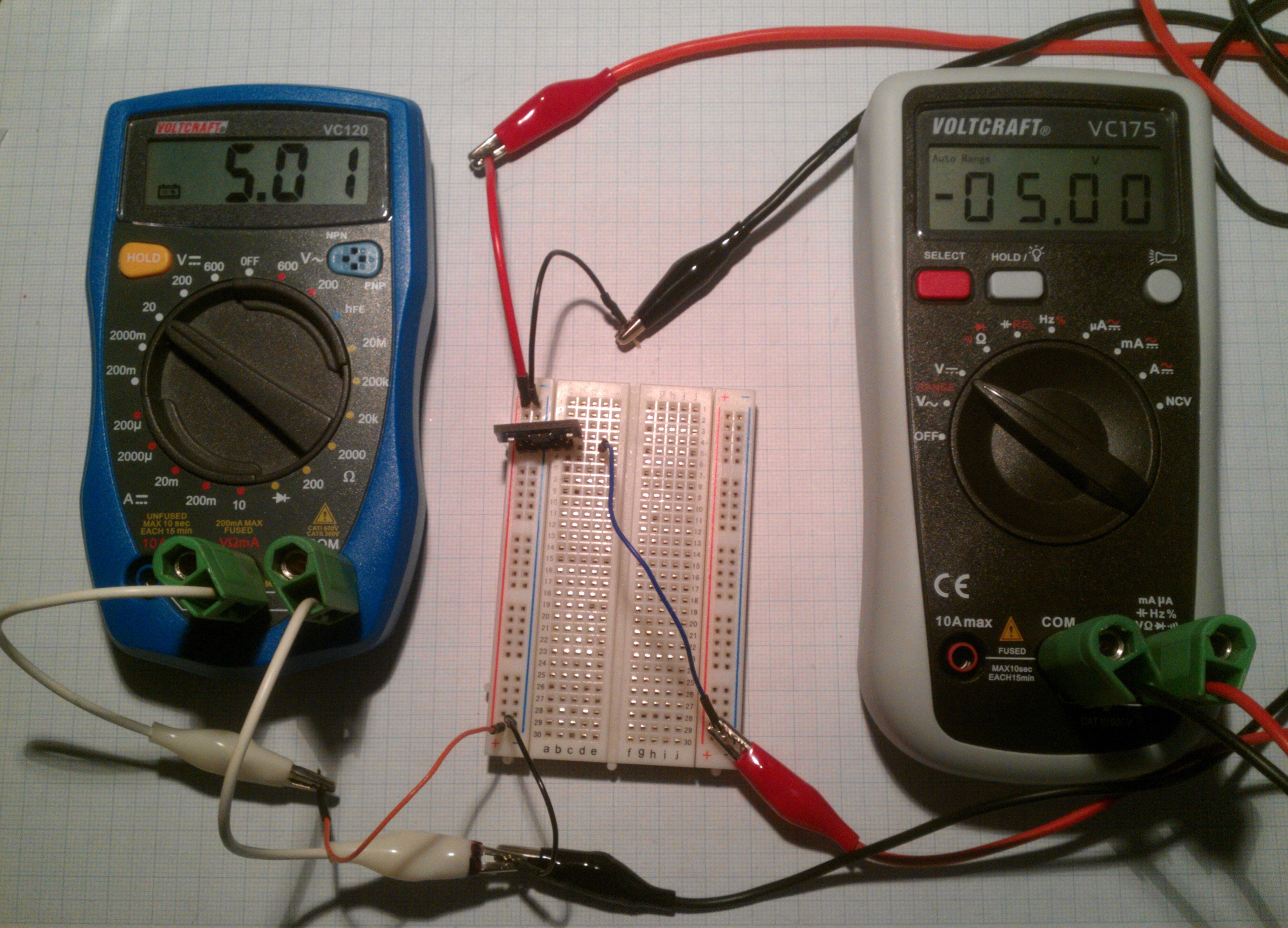
This is another one of @SUFs contributions, the original files of which can be found here. It's a negative voltage converter based on the Intersil ICL7660S and works quite well as you can see:

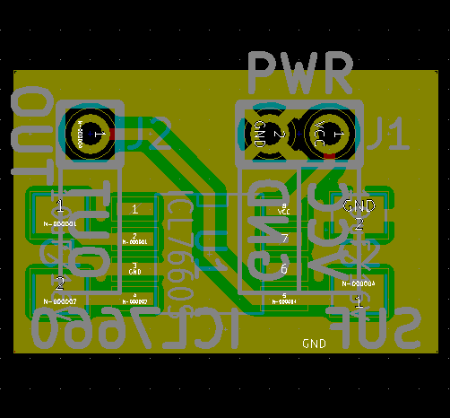
Here are the original schematic and board layout:

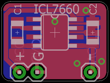
Since I mainly use Eagle, I remade it trying to stay as true to the original as possible.

However, since I wanted to make it as compact as possible (reducing the 'overhang' on the side of the pin headers) I ran into the problem of all the GNDs not connecting which required a slight rerouting to keep everything on one layer which is an advantage if you would like to etch it yourself (the GND vias are only redundancy).
... I can already feel the onset of feature creep caused by the empty bottom layer...
Update 2016-01-05:
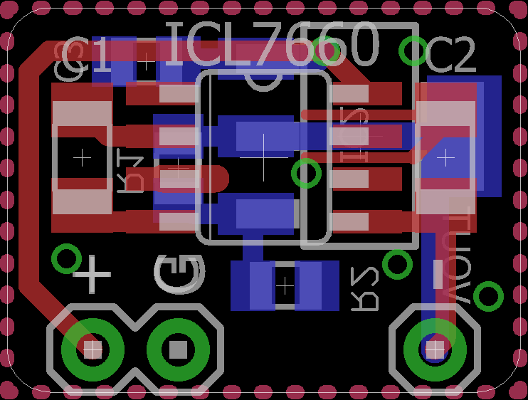
I'm putting together another panel and wanted to include this board but since I'm not going to need ten of these I put a LD/LM1117 footprint on the back.


The board has footprints for resistors to adjust the voltage but if you use a fixed voltage device you can just short R2 to connect Adj to GND.
 Stefan Lochbrunner
Discussions
Become a Hackaday.io Member
Create an account to leave a comment. Already have an account? Log In.
If you put the connector at the right hand side of C2 or upper right corner, then all the traces lines up.
Are you sure? yes | no
But if you put the connector to the upper corner, the board will not fit into the breadboard vertically as it was designed for.
Are you sure? yes | no
Hi Steve,
Just for the records, here is the picture of the original schematics:
Are you sure? yes | no
Thanks, I replaced it above since the schematic symbol of the part I used had the pins in a strange order which was somewhat confusing. The package pinout was identical though.
Are you sure? yes | no