As per @Howard Jones' suggestion I've made a breakout board for the following D-sub connectors:
- DA-15
- DB-9 (or more accurately DE-9)
- DE-15 (VGA)
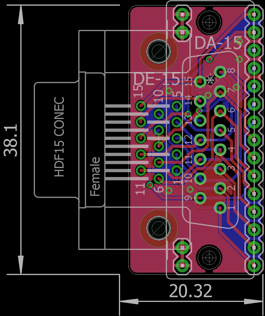
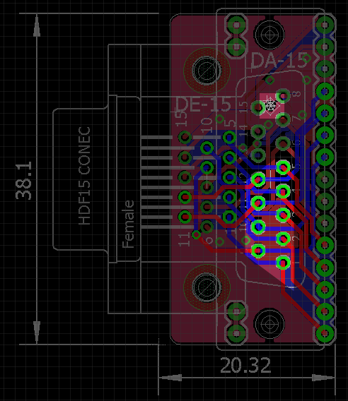
I'll spare you the (obvious) schematics (<- GitHub) but here's the board:
From the original version I switched to a slightly different DE-15 footprint whose rows of pins are a little further apart which seems more common. I also added two 2x1 headers to connect to the GND rail of a breadboard int order to ground the shielding and to better fasten the board.
I mentioned that I used the DA-15 footprint simply because there are already 15 pins on the board and it has the same spacing as a DE-9 so why not (even if it requires some modification). To use a DE-9 connector I thought one would use the lower nine pins and make a new mounting hole like this:
The upper highlighted area is where the connector's other shield connection/mounting point would be. There's already a small hole there so in order to attach the connector you can extend the hole to the required size without damaging relevant traces.
 Stefan Lochbrunner
Discussions
Become a Hackaday.io Member
Create an account to leave a comment. Already have an account? Log In.