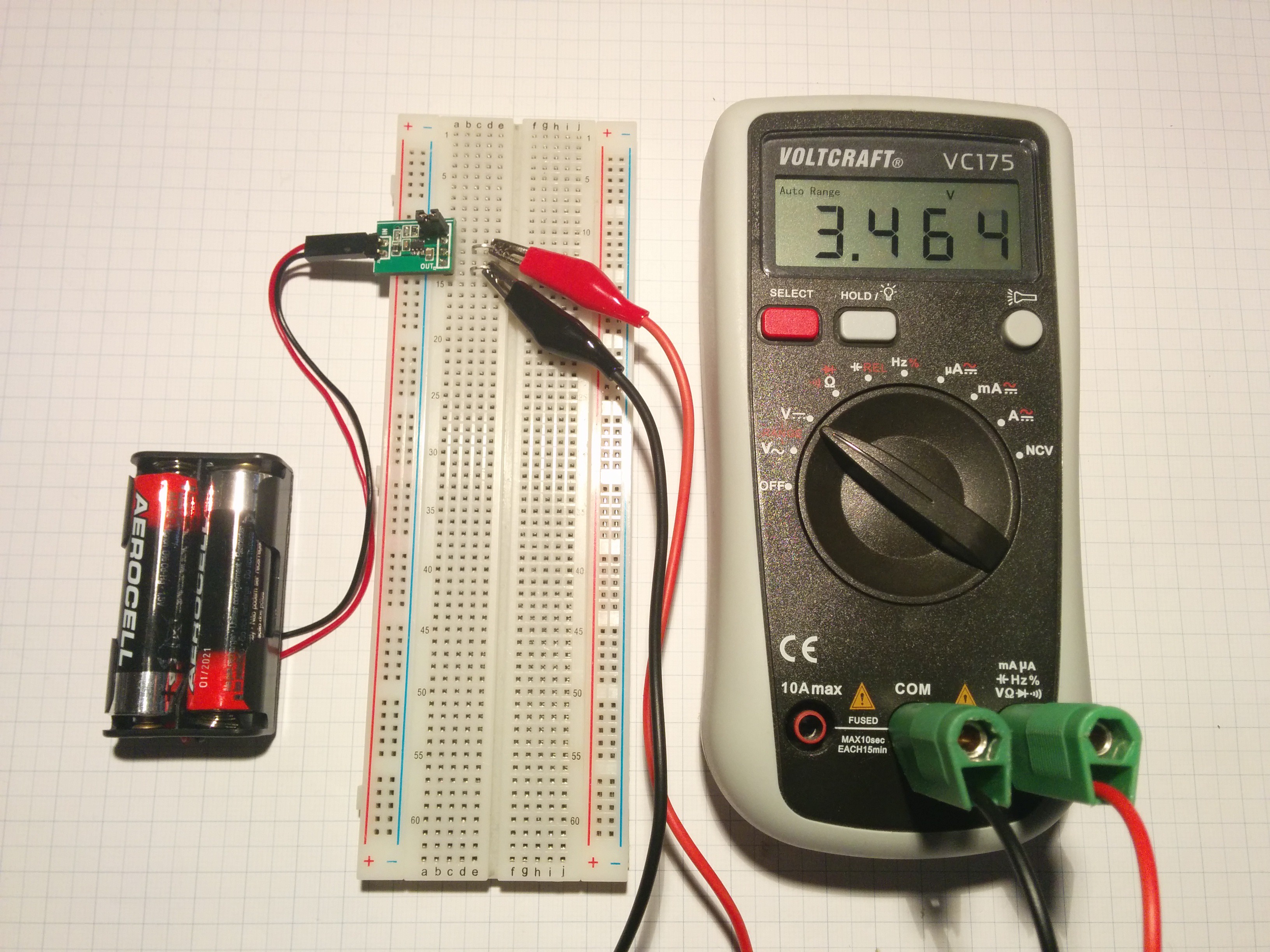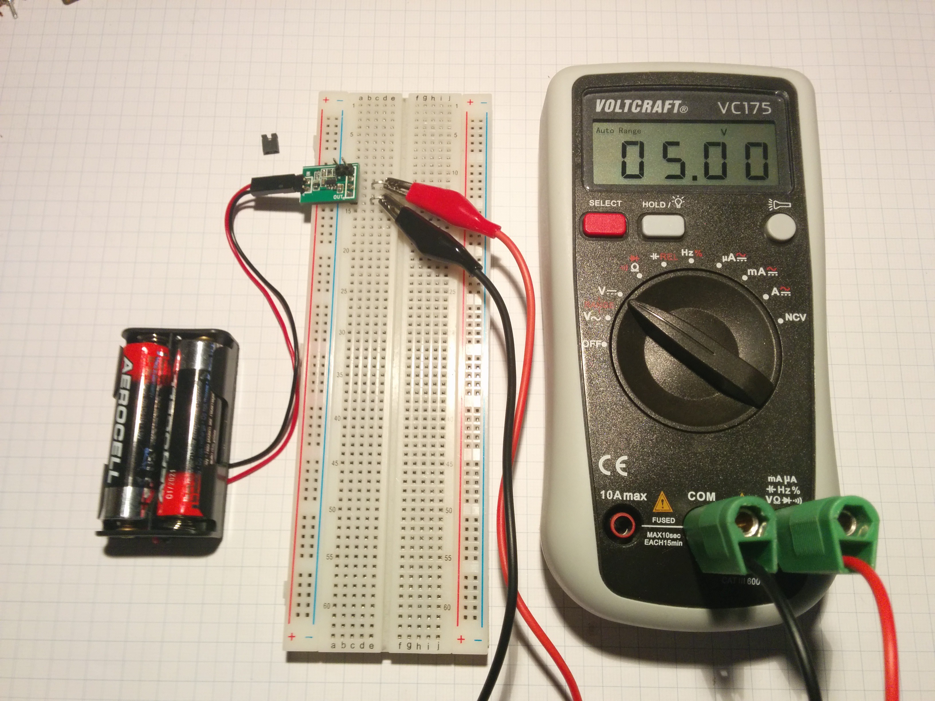
@SUF kindly supplied me with another one of his very useful widgets. This time it's a breakout for the MCP16252 boost regulator that can be configured to output either 3.3V or 5V by setting or removing a jumper respectively:


SUFs original post about the board can be found here which also shows the original design. My EAGLE remake can be found in the GitHub repo as usual.
As you may expect I completely obsessed over making my redesign of the board even more breadboard compatible than it needed to be up to the point of it being not very practical. Initially I wanted the board to be able to supply power
- to the power rails from the battery pack,
- to the rails from a source inside of the breadboard and
- to the inside of the breadboard from the power rails.
After not making any significant progress with this idea (and taking way too much time) I decided to step back and and share the board in its current form:


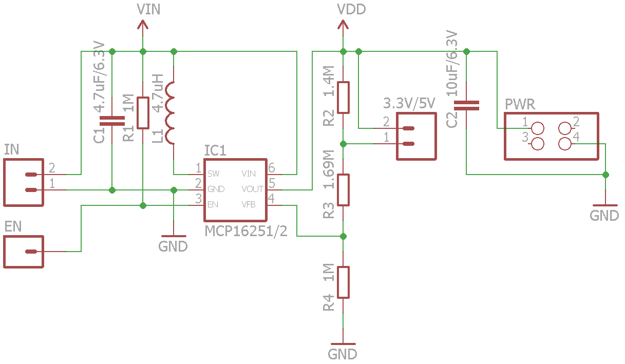
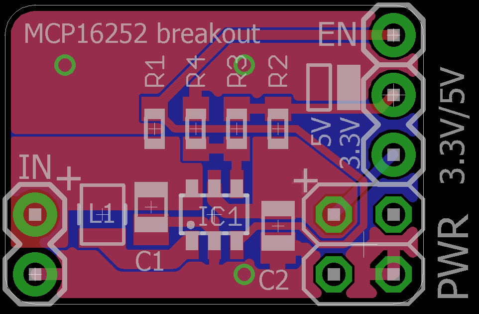
The schematic is pretty much identical to SUFs version while the layout has been slightly altered to allow the power pins to be plugged into the power rails and the enable pin to be plugged into the inside of a breadboard. I tried to keep as true as possible to the reference design and keep it on a single layer.
Many thanks to @SUF for all his contributions to the project and my apologies for taking so long with this write-up ;)
 Stefan Lochbrunner
Discussions
Become a Hackaday.io Member
Create an account to leave a comment. Already have an account? Log In.