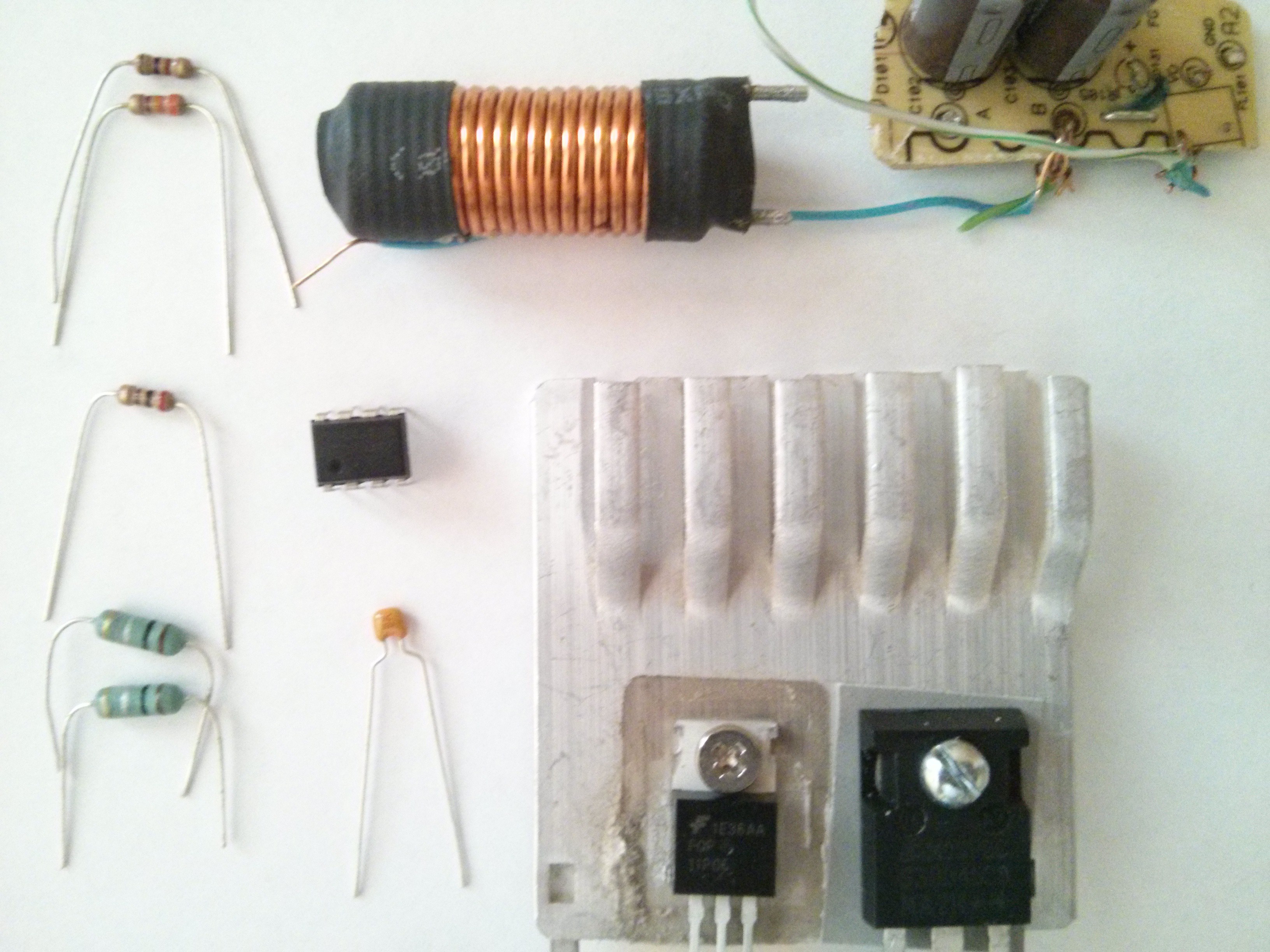
A family photo of all the parts that went in. However, the heatsink was removed when it became apparent that i would have space constraints. The capacitors were switched out as well. Not shown is a USB hub I burnt out a while back that I used for the USB ports. The FET is rated for ~11 amps continuous and the diode is rated for 20 amps. The diode was one I pulled out of a ATX power supply.
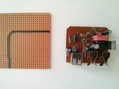
 Outlining the board.

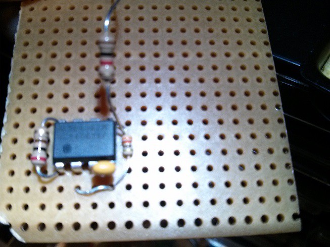
Adding Parts. The 1k resistor was later relocated to underneath the board.
Here is where life got busy and the project was put on hold for about two weeks.
Discussions
Become a Hackaday.io Member
Create an account to leave a comment. Already have an account? Log In.