Close
0%
0%

3D Compass

Visualizing the Earth's magnetic field vector in its three dimensional glory.

Similar projects worth following
The Earth's magnetic field changes with time on many scales and has a dip angle as well as 2D projected "direction". This instrument is a fun way to visualize the 3D orientation of the magnetic field at your location and to monitor its changes on the diurnal and yearly scale.

Any fine details and lots of photos/resources/links are in the GitHub repo. You can learn a lot from your new compass/magnetometer! In addition to learning about the electronics and hardware, you can learn about magnetic fields and the Earth's geodynamo.

  • 1 × Arduino Uno
  • 1 × NeoPixel Ring - 16 Element
  • 1 × NeoPixil Ring - 24 Element
  • 1 × 1000uF Capacitor - 6.3V or higher
  • 1 × HMC5883L Magnetometer Adafruit Breakout

View all 10 components

  • 1
    Step 1

    3D Printing Brackets

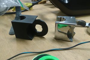
    - Print 1 top and 1 bottom bracket. 60% infill and a raft are recommended.

    - Using a soldering iron, insert the heat-set thread inserts. Eight in

    bottom plate, 4 in riser posts, 4 in Arduino mounts. Two in top plate for

    magnetometer mounts. See the demo video below (not mine, borrowed)

  • 2
    Step 2

    Top Plate Assembly

    - Attach the magnetometer with 4-40 nylon screws. Shear the excess length flush

    with the bottom of the plate using a hobby knife. Be careful to not break

    the superstructure on the printed part.

    - Place the capacitor into the cut-out and secure with a drop of hot glue.

    - Solder ~5 cm of wire onto the data in line on the 16-element ring.

    - Place the 16-element NeoPixel ring into the vertical ring holder. Thread the

    data-in line through the hole in the bracket. This ensures that data-in, V+,

    and GND are all accessable. Secure with a drop of hot-glue.

    - Place the 24-element NeoPixel ring onto the riser posts. Line up the data-out

    pad to be near the data-in line on the smaller ring. The LED should be directly

    above the mounting post. Secure with hot-glue on each post.

  • 3
    Step 3

    Bottom Plate Assembly

    - Secure the Arduino RedBoard to the base plate with 4-40 nylon screws. Shear

    the excess length flush with the bottom of the plate using a hobby knife.

View all 6 instructions

Enjoy this project?

Share

Discussions

Similar Projects

Does this project spark your interest?

Become a member to follow this project and never miss any updates