PiBooth
RaspberryPi photo booth to help capture memories at your events.
RaspberryPi photo booth to help capture memories at your events.
To make the experience fit your profile, pick a username and tell us what interests you.
We found and based on your interests.
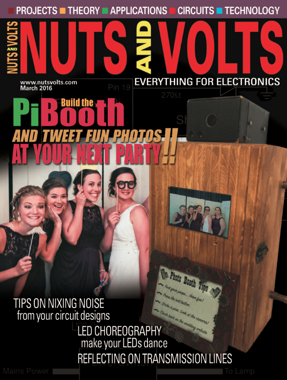
The PiBooth was a great success! It has performed at our wedding, a second reception, a friend's wedding, and a few other small events. The Twitter functionality works great and a mobile hot spot makes it all ready to go wherever we take it. The PiBooth was even on the cover of Nuts and Volts in March 2016! Feel free to adapt whatever you'd like or file issues if you have them, but so far the code base seems very useable for all who have tried!
I fixed some of the code regarding the resolution of the images to provide better shots. Updates are on the project github (https://github.com/jrleeman/PiBooth) and work great. Working on an instruction sheet to paste on the front now, but I think we're pretty much ready to go with this project!
I added a cap across the photo button terminals to try to prevent the false triggers, not expecting much.... And it didn't work. So, I decided that the solution was in software. I added a sleep in the callback functions tied to the button presses. The photo button sleeps for 0.1 seconds, then checks to make sure the button is still low. The shutdown button checks after 3 seconds to make sure you really meant to power off the unit. That did the trick! No more weird triggering due to light switches, power pulses from the AC, or just random noise. Now I just need to add some finishing copper trim to the box and find any last minute bugs. I think this project is in the home stretch!
A few photos of putting "the big red button" that starts the photo taking process in a diamond plate case from Hobby Lobby. I used antenna rotor wire for the cable and a 3 pin connector from Amazon. The connector is a little hard to connect/disconnect, but hopefully it wears it well. The button has an LED in it (hence the three wire cable), but I was totally underwhelmed by it's brightness and coverage, so I opted to not connect it for the time being. Don't forget a grommet to prevent wire damage from the metal box!
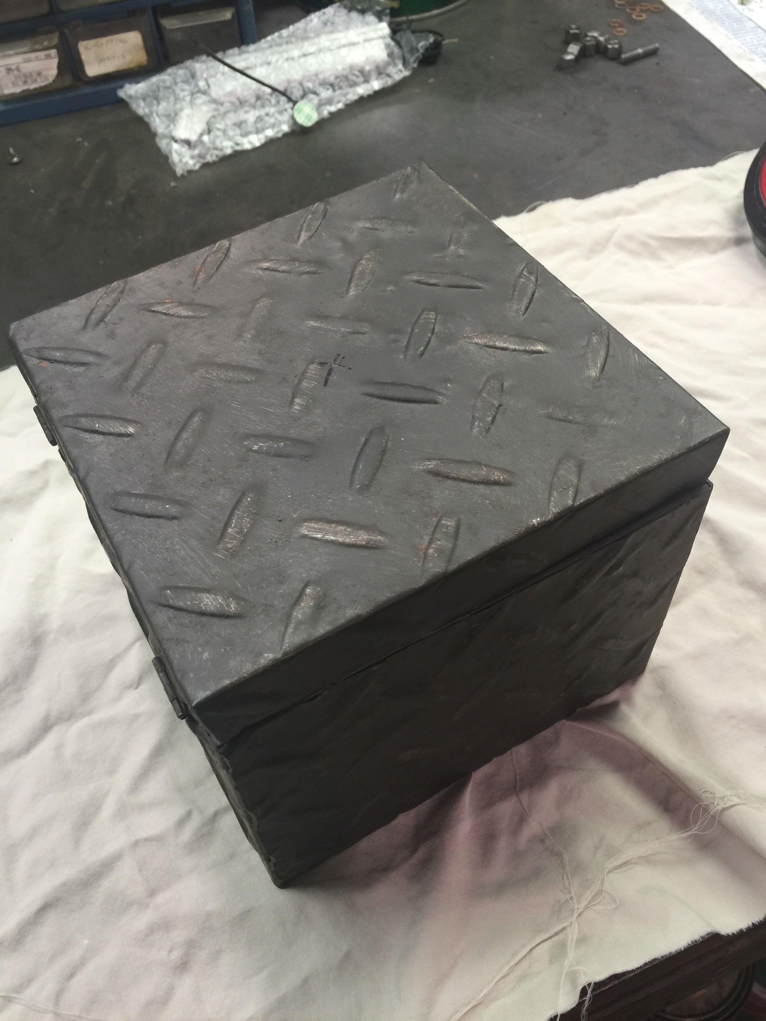
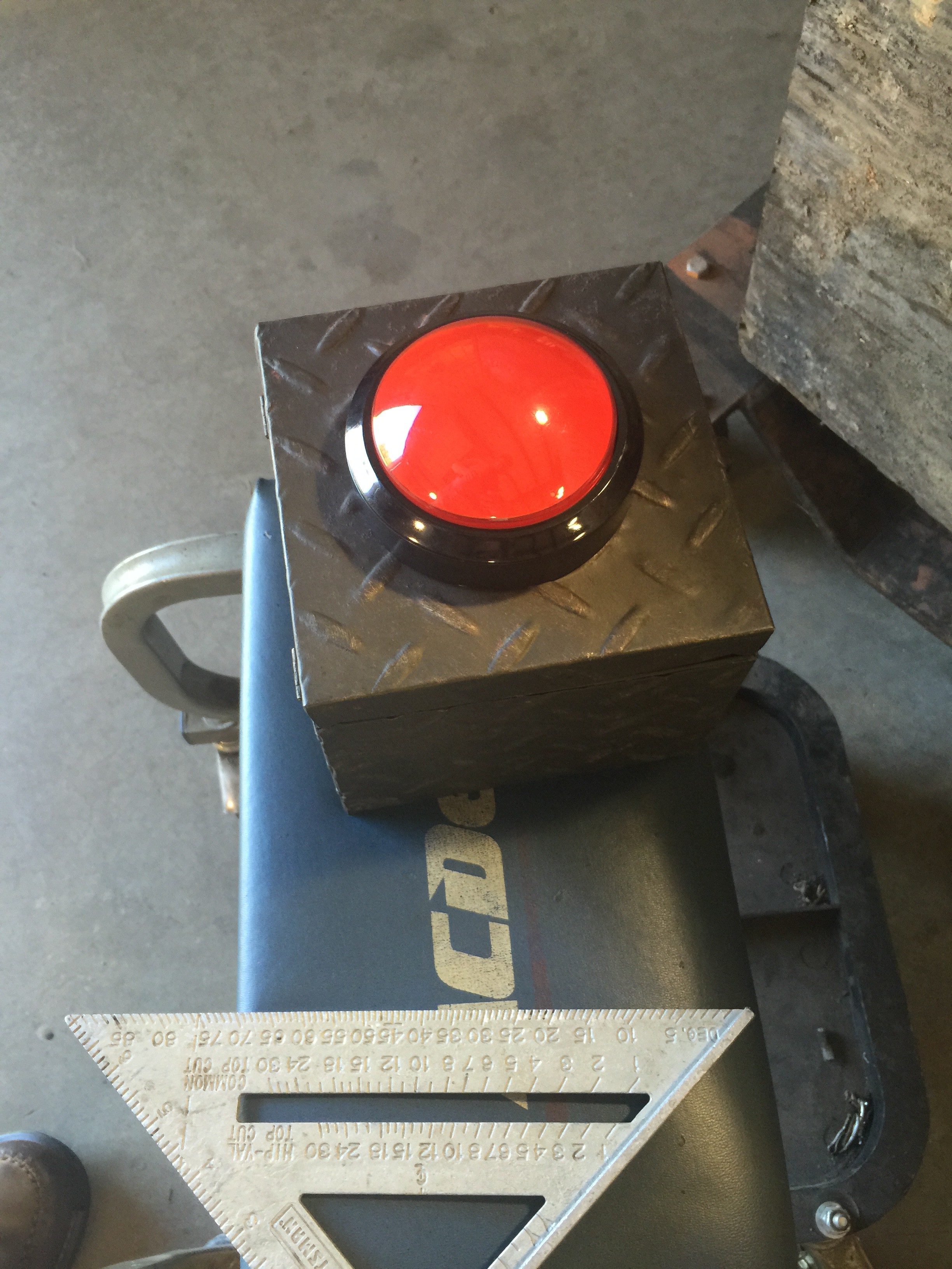
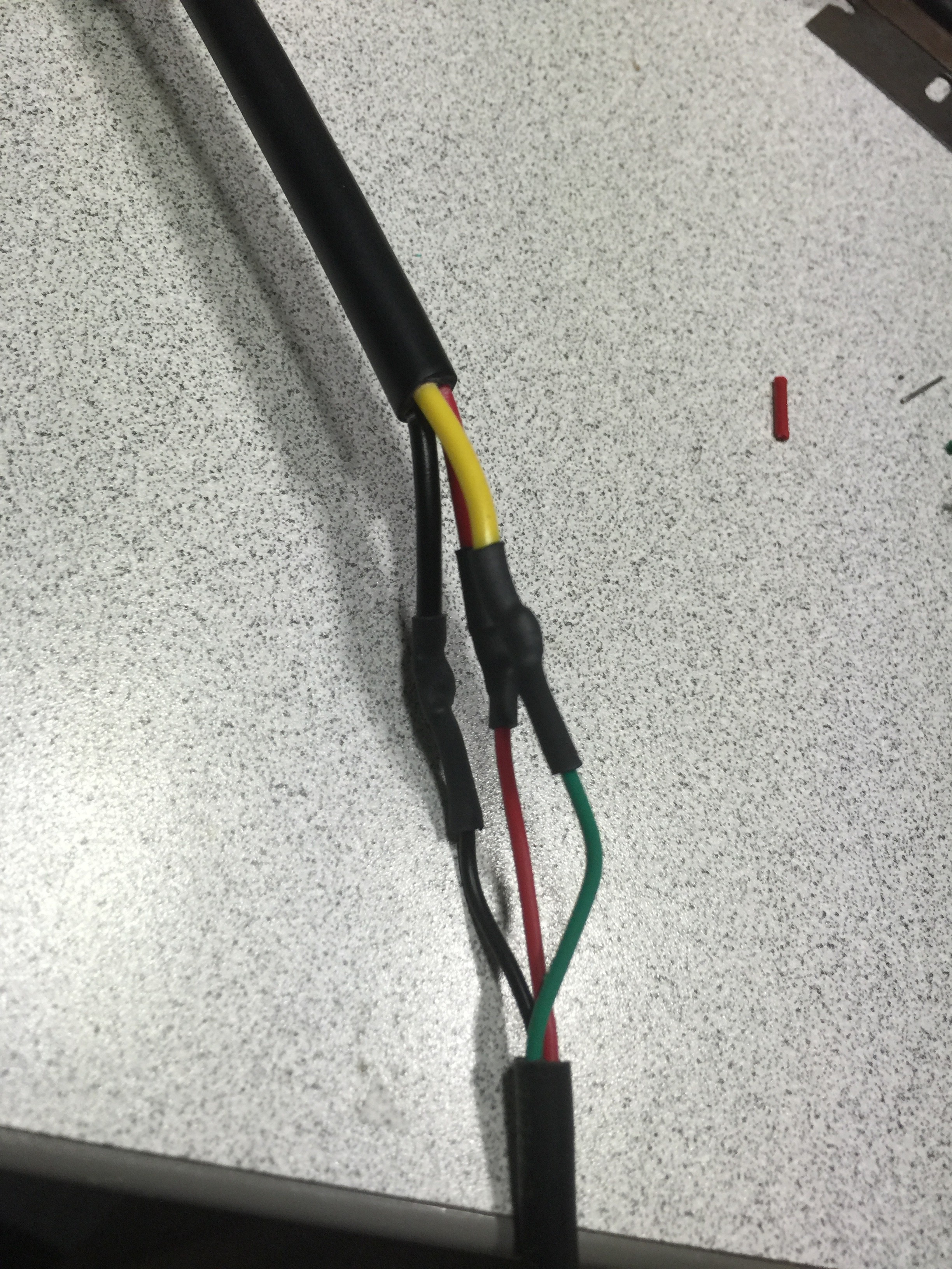
Almost there! I just have one small cosmetic detail left I think. I added the shutdown button to the back panel and mounted the big button in a box with long cable and connector. The back cord hole is felt backed for better appearance as well. A couple of concerns have come up:
- Sometimes the photo sequence false triggers from interference on the button line with the long lead. It's annoying at best, but if it also gets into the shutdown line it would make the unit unreliable.
- It gets warm inside. Not too much to be worried, but something to keep an eye on I suppose.
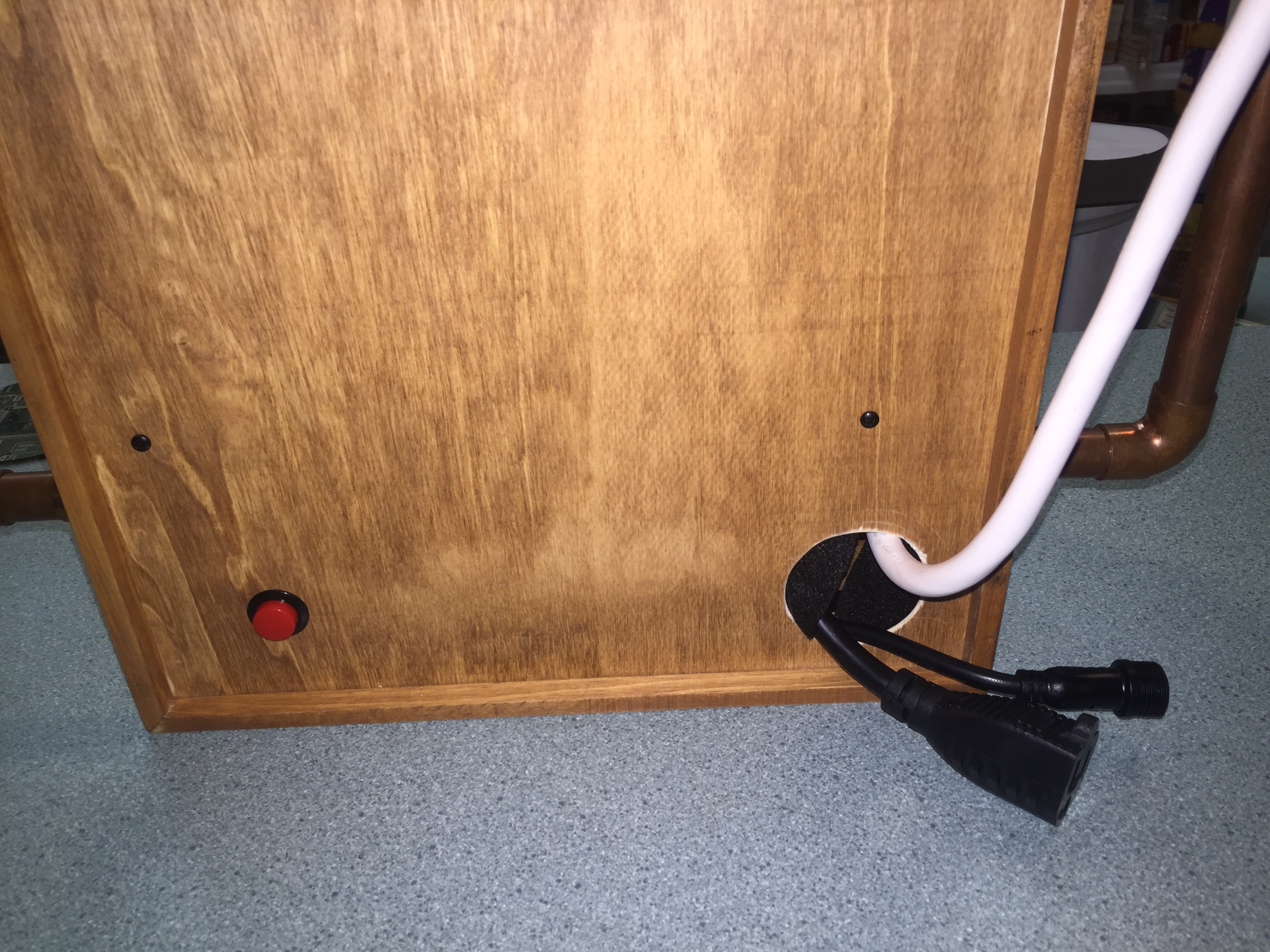
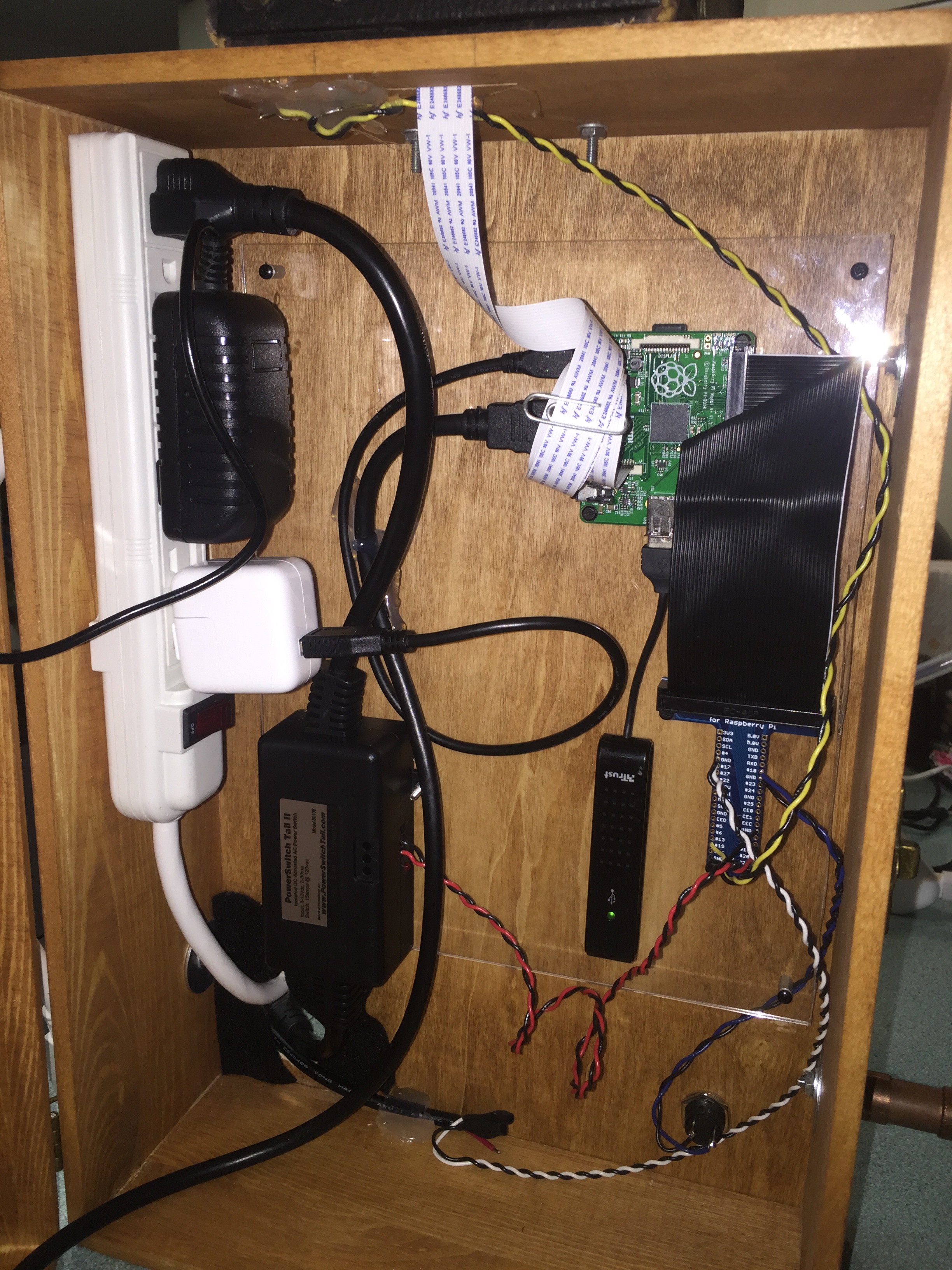
I cut a sheet of plexiglass to use for a backplane. The Pi, hub, breakout, etc were all mounted with standoffs and 4-40 hardware. The backplane was then mounted to the cabinet in the same way. This looks like it'll be a really nice way to keep everything organized and from touching/shorting. I also drilled and mounted the handles with fender washers. Everything powers up, but there are lots of small details to finish like the button to take photos and shutdown. A 1.25" hole in the back lets the power cords for the power strip and line switch out.
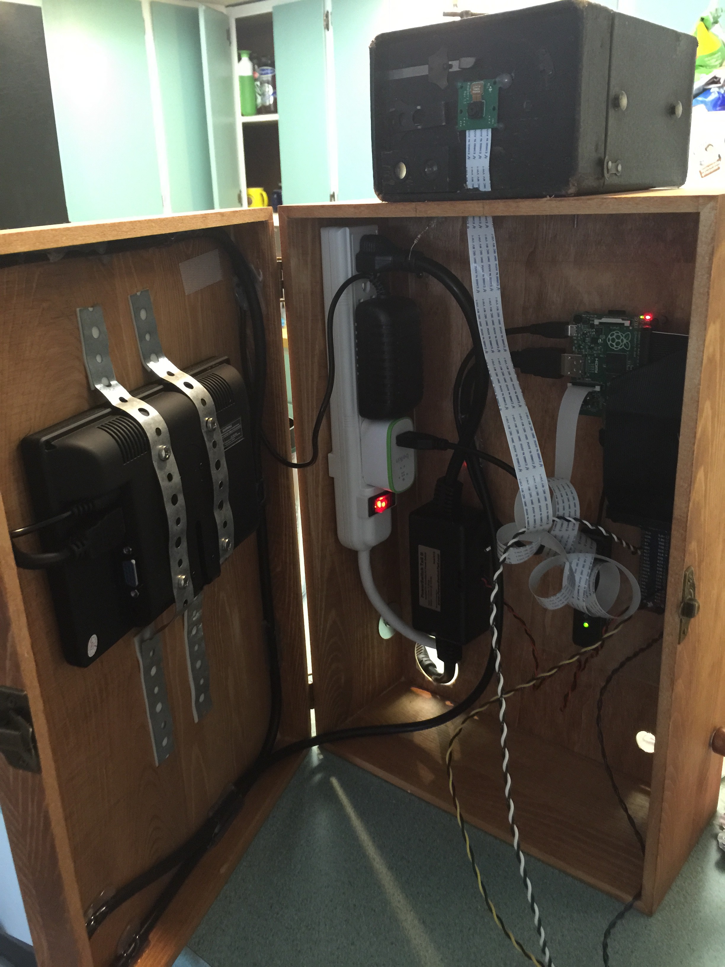
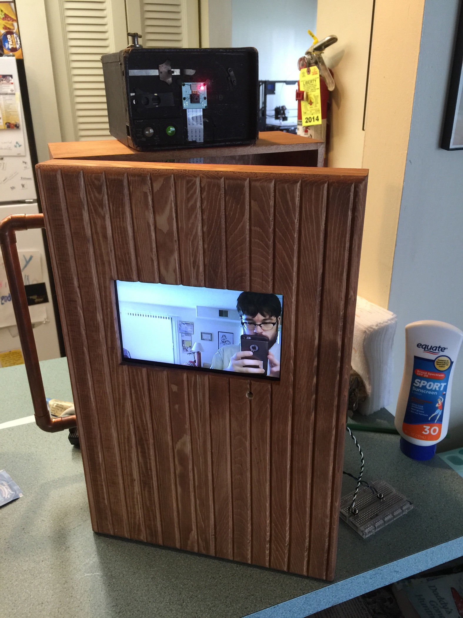
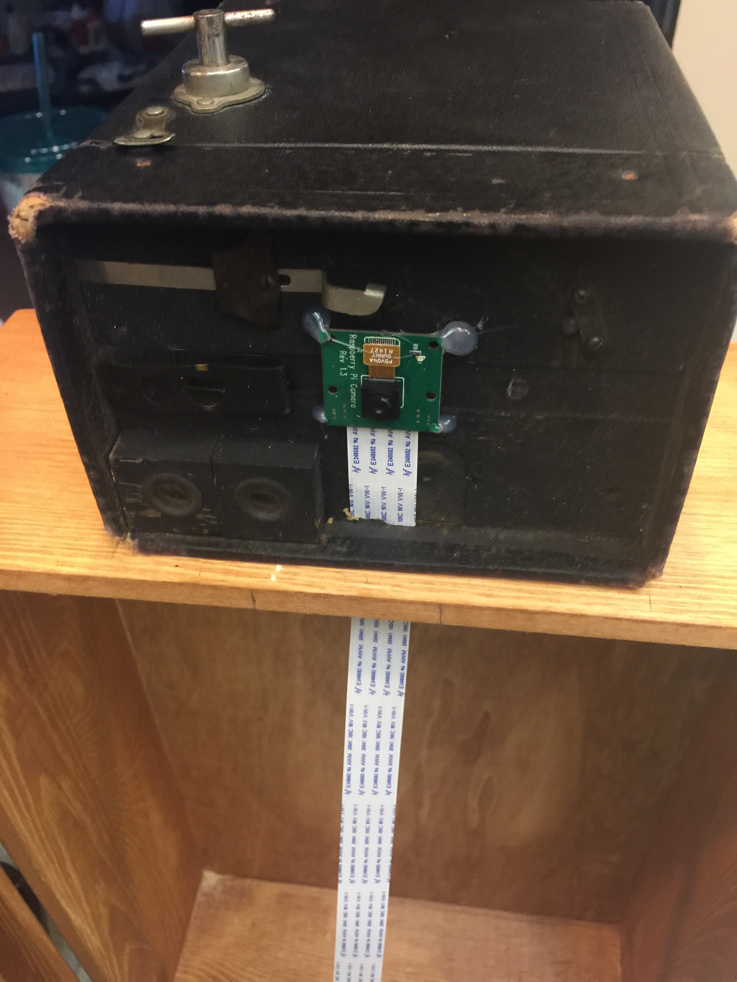
I mounted the Pi Camera in the shell of an old Kodak brownie camera. This was a $15 antique shop score that was very easy to modify. I also removed one of the viewfinder lenses and will shine the flashy LED that shows a photo is being taken though it. This will show through one of the ports on the front near the camera. The ribbon cable fed nicely through the slot.
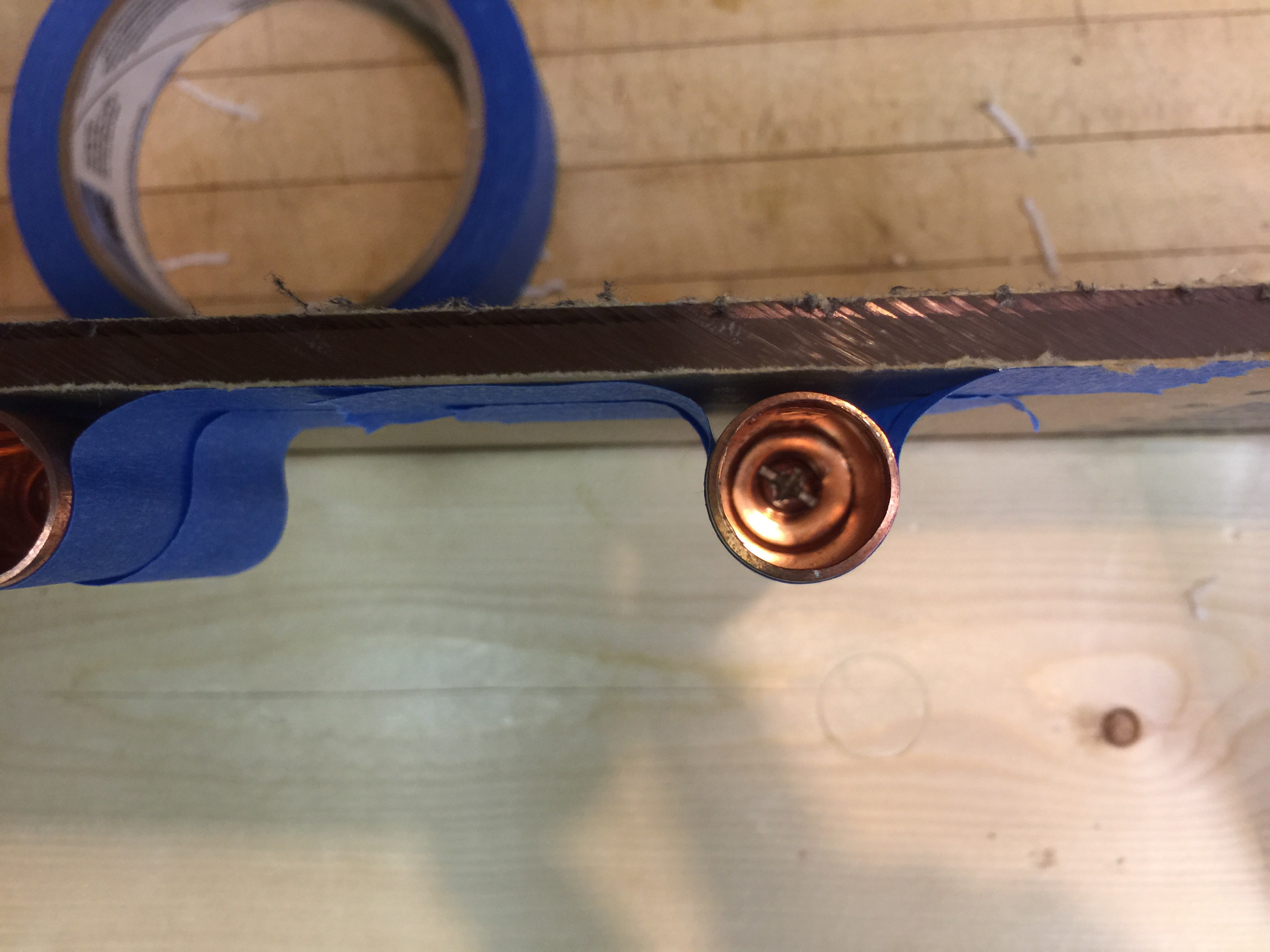
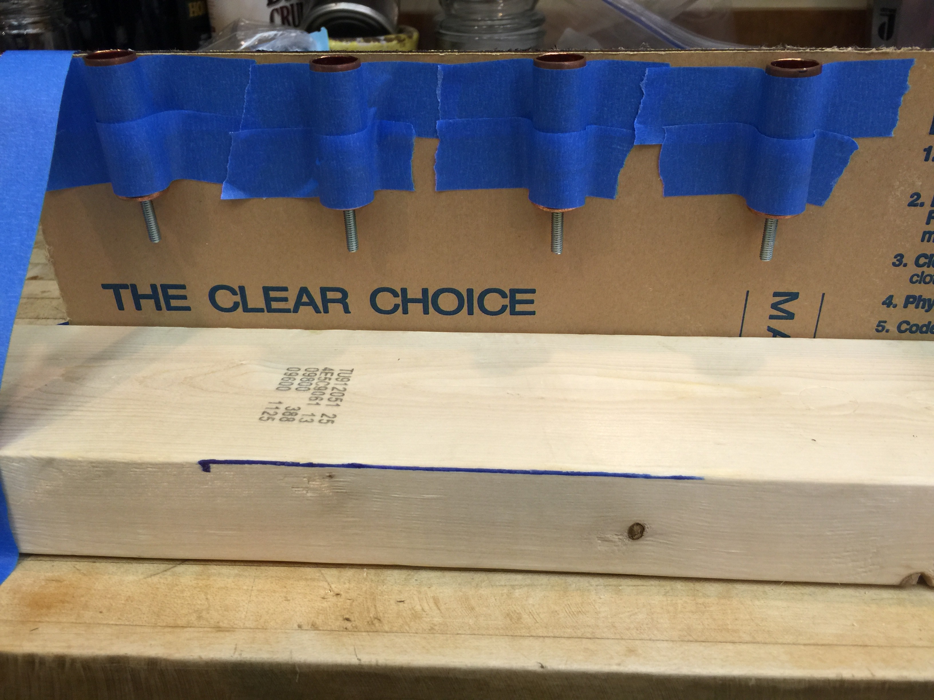
I also used some 1/2" copper tube to make a nice set of handles for the box. I drilled the end-caps to fit a machine (size 8) screw. The screw was then super glued to seal the hole and two-part epoxy poured over the top. This effectively made it a stud. The handles will be mounted to the box with fender washers so that the wood should be harmed when picked up.
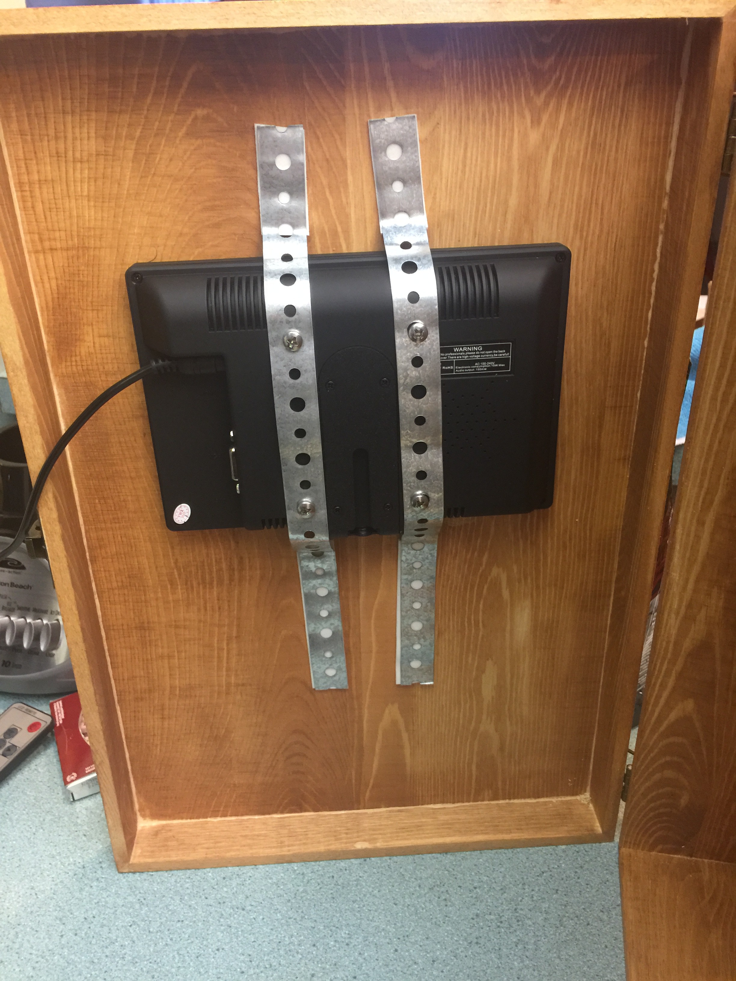
The monitor is mounted using some M4 screws and plumbers tape. I also had to drill a hole for the IR sensor to be able to control the monitor. The remote is secured with some velcro, it's easily removed, but hopefully I won't lose track of it! I also prepared the area where the camera will be mounted. I drilled a hole and then used a jigsaw to make a slot for the PiCamera ribbon cable.
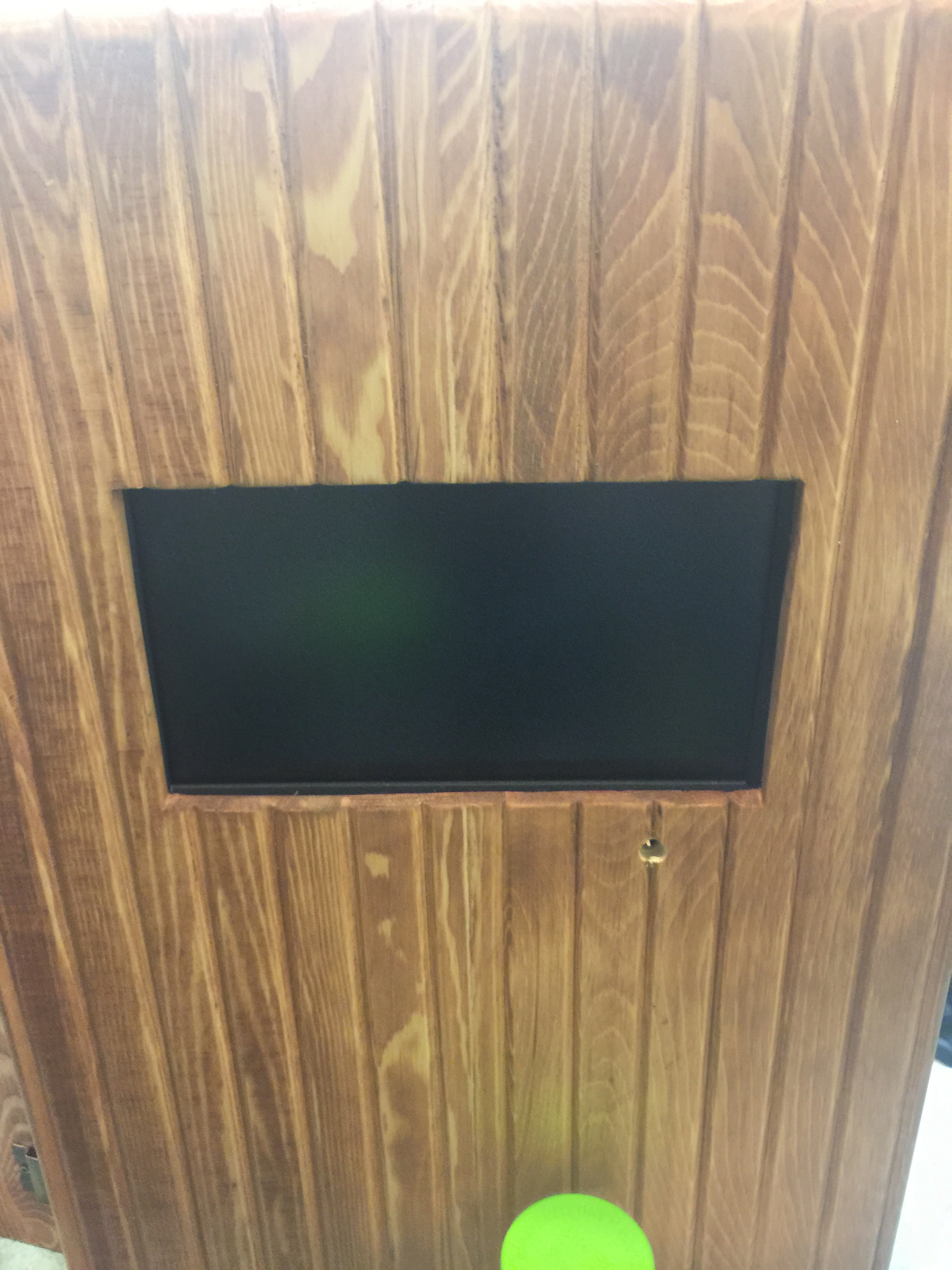
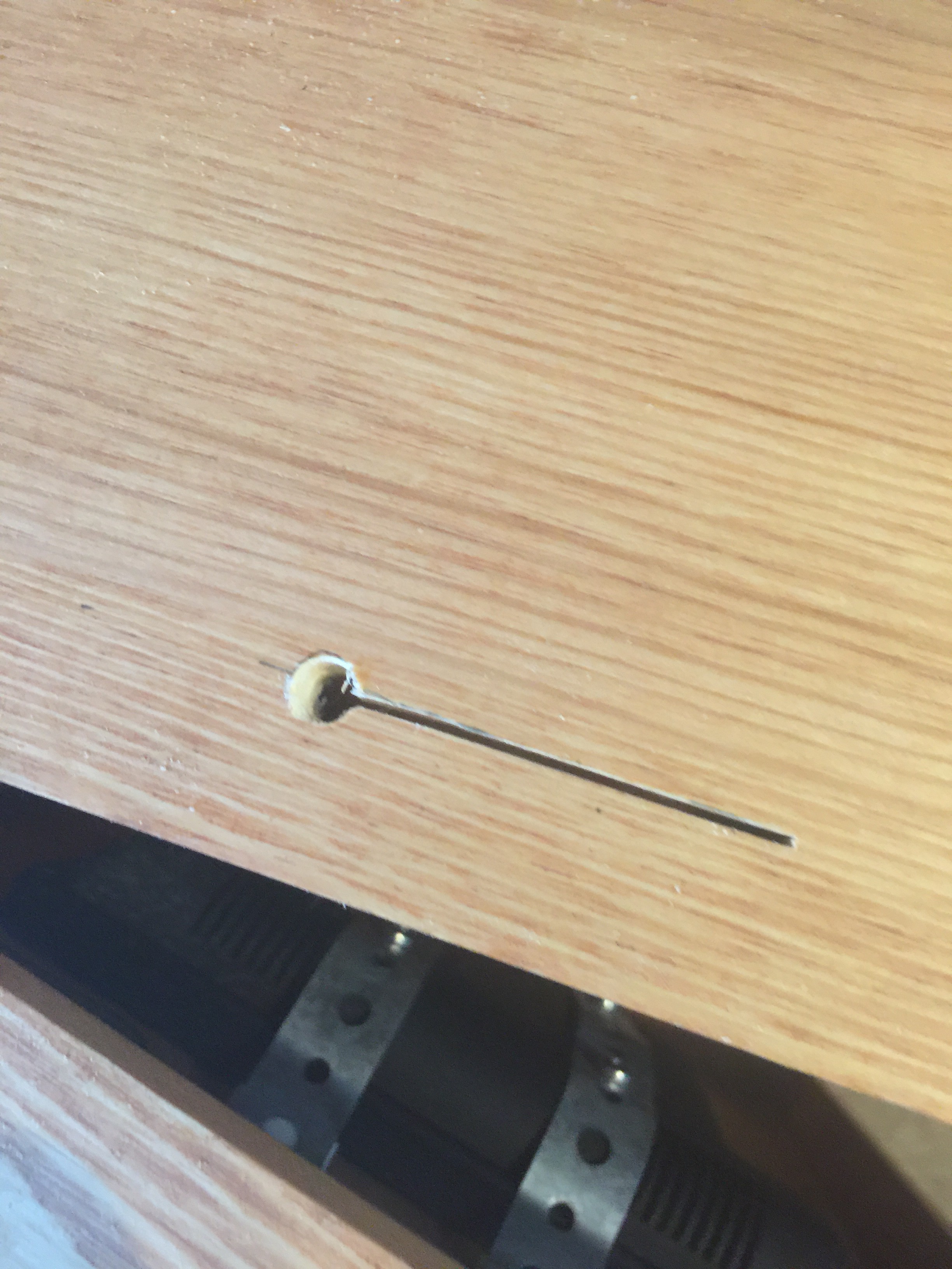
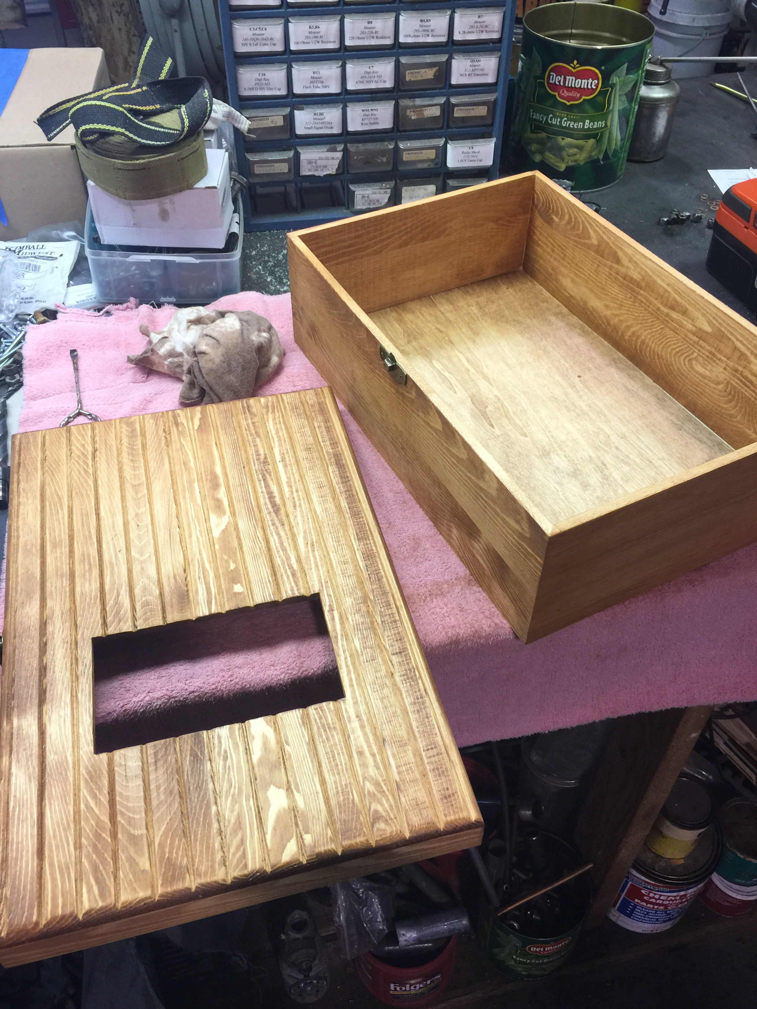
I found a wooden box at Hobby Lobby that almost perfectly fit what I wanted for the project. I cut a template for the screen size and drilled holes at two opposite corners of the screen area. Then, using a jig-saw, I cut out the screen area and fine tuned it with a wood rasp. I stained the box after extensive sanding with cherry stain.
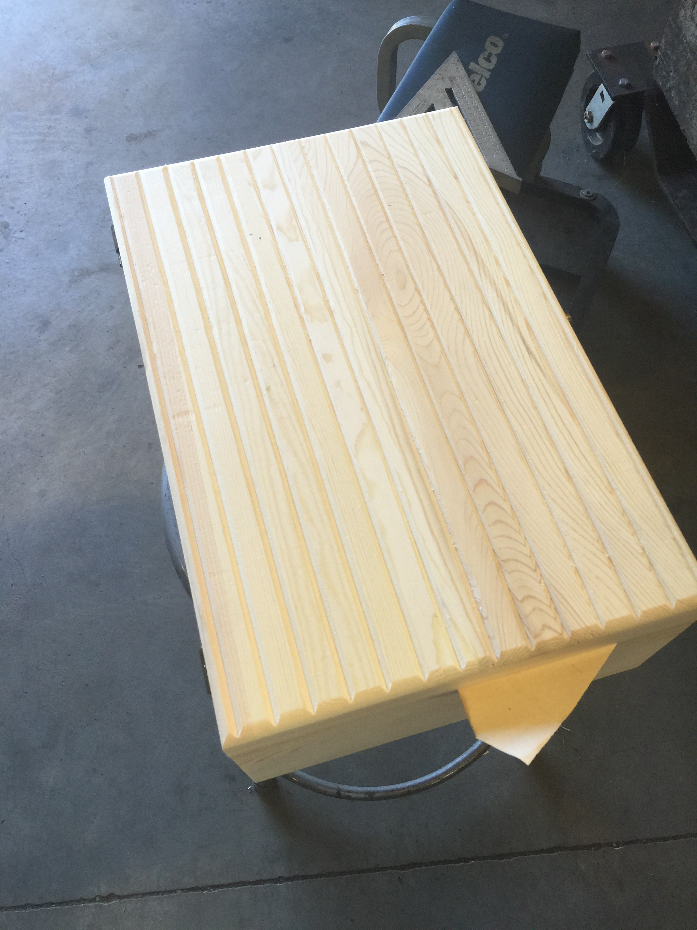
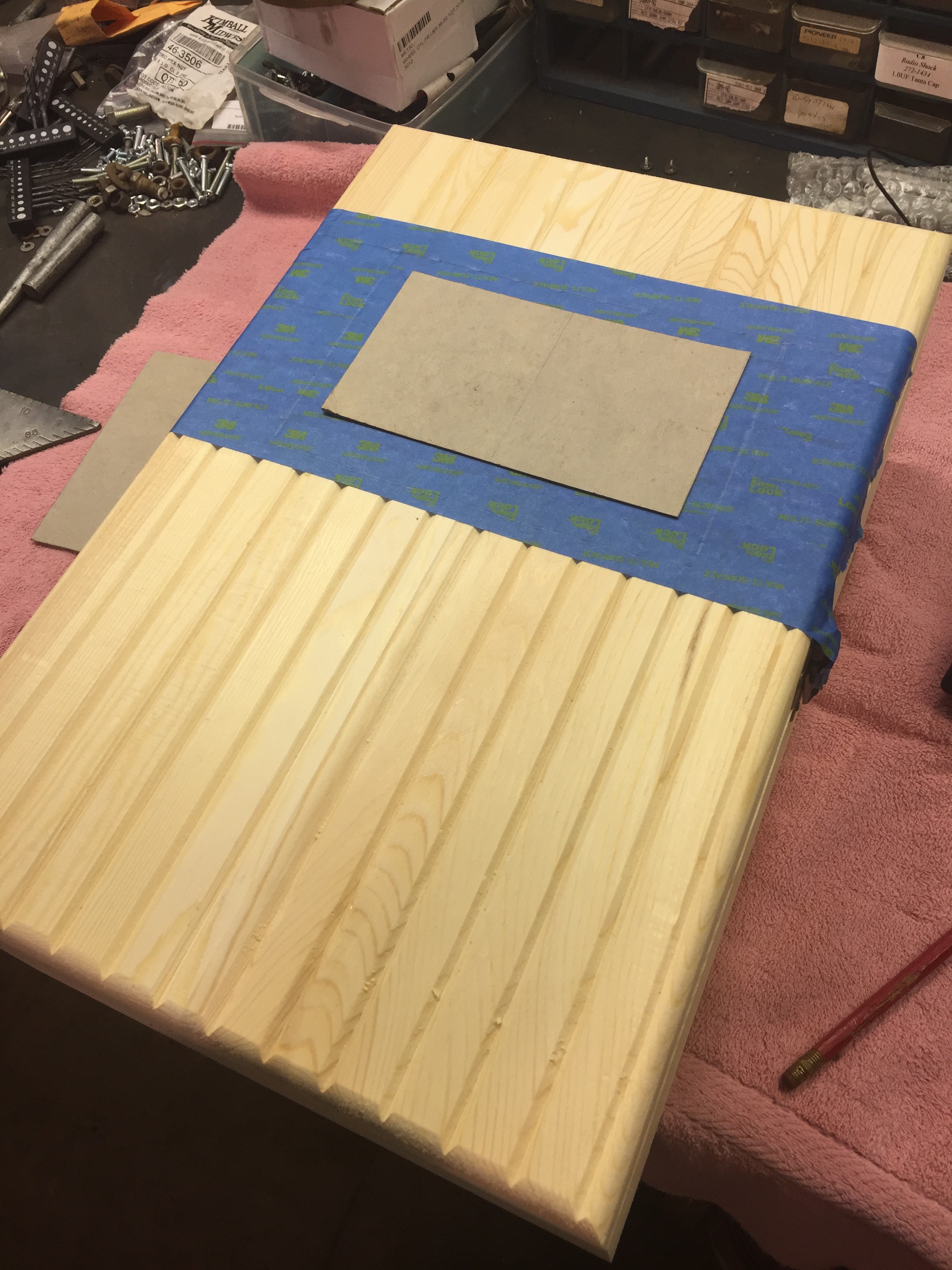
Over the last week I've got the PiBooth tested out and am ready to design the case for it. After receiving my last order of parts, I hooked up the power tail and tested the setup with a lamp. Everything looks good! I also added functionality to adjust the contrast and brightness settings with arrow keys on the keyboard. My next big task is to build the case and get things installed. I won't write detailed case instructions since everyone will want to build their own unique style, but there will be lots of build photos! In the mean time, here's a video of the operation on a large screen.
Create an account to leave a comment. Already have an account? Log In.
If you have a camera that supports it, that may be possible. I haven't played with gphoto2 much, but it could work. I'm not sure how the live preview would work though.
Become a member to follow this project and never miss any updates
By using our website and services, you expressly agree to the placement of our performance, functionality, and advertising cookies. Learn More
Is it very difficult to change the code to use gphoto2 (dslr camera)?