J. M. Hopkins
-
Launch Schedule and More
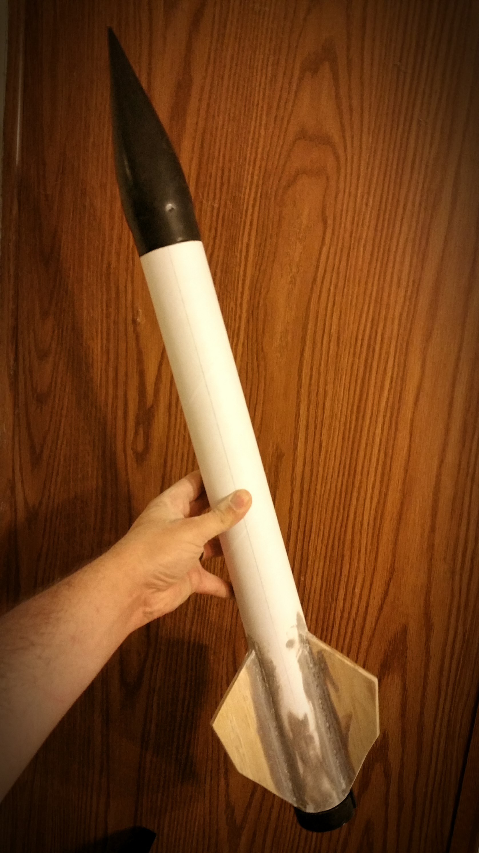
03/06/2016 at 03:14 • 0 commentsTime goes by fast... Next week is this month's club launch and I have a lot to do. This month's launch will have 2 static tests, and 2 rocket launches if all goes well.
Static test - 5/16" throat 4 grain 38mm H-250 test - focusing on testing of new grain separation construction technique and obtain thrust curve of this new motor via my new 70cm Serial to WiFi Bridge hardware.
Launch of H-250 - Focusing on motor performance under flight conditions, confirming techniques demonstrated in the static test. I'll be using a smaller rocket with single deploy to ease the electronics package to small size.
Static test - 7/16" throat 6 grain I-550, focusing on obtaining thrust curve and confirming construction techniques used with new grain separation paradigm.
Launch of I-550 - Demonstrating at altitude RF communication and motor performance.
All in all it will be a packed day.
This i still need to do before next weekend:
- Cast fuel - 38mm, .652" bore - 8x2.75", 10x2.5", 2x4" grains
- Finish small rocket (Wood fill, sand, and paint)
- Finish large rocket lower half (top half and AV bay are from last flight's CATO)
- Prep and pack
The fuel is the difficult part, the rocket body work still time consuming. Luckily I have 4 nozzles complete and just need to compete the fuel.
Here's a picture of the small rocket getting finished:
![]()
Stay tuned for more updates as next week's launch date comes closer! And please don't hesitate to ask questions about any of this project.
-
70cm Serial WiFi Bridge Complete
03/01/2016 at 02:32 • 0 comments -
WiFi Serial Bridge LCD
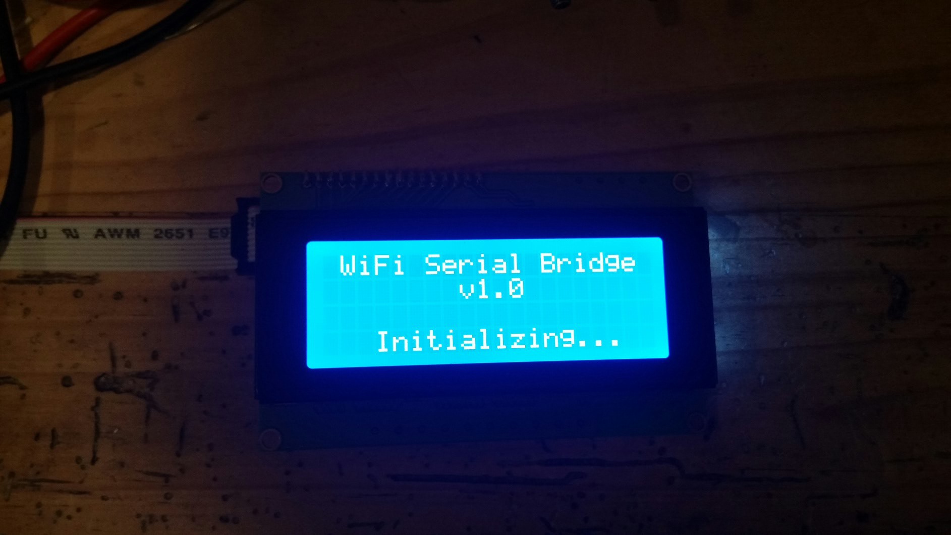
02/29/2016 at 04:25 • 0 commentsI will make a separate project page for this little device, but for now I'll give another update.
I've added a 20x4 LCD off of the ESP8266 via I2C, anything coming through the UART to the telnet session within brackets will display on the LCD. This allows for succinct messages to be displayed with ease from attached devices.
![]()
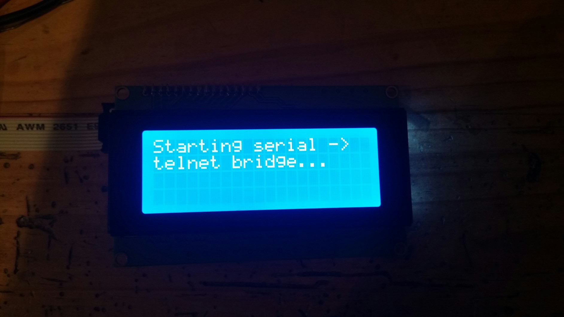
The initialization screen of the wifi serial bridge...
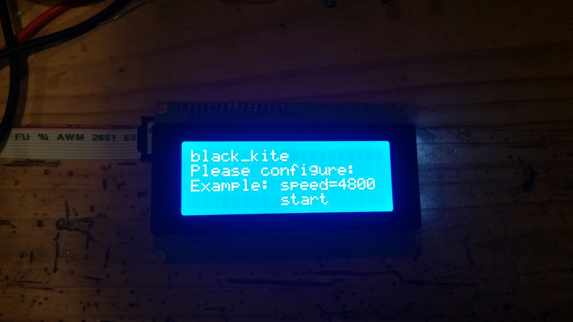
![]()
The option to configure settings such as UART rate, SSID etc. By connecting via telnet and typing "start" the defaults are loaded from EEPROM and applied.
![]()
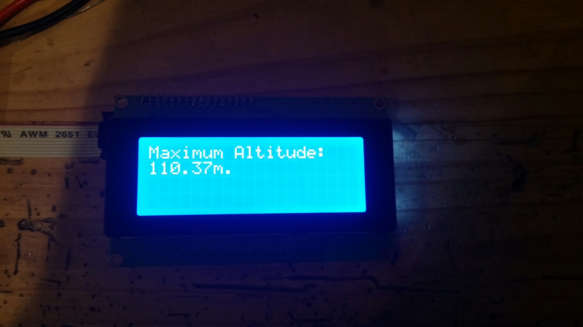
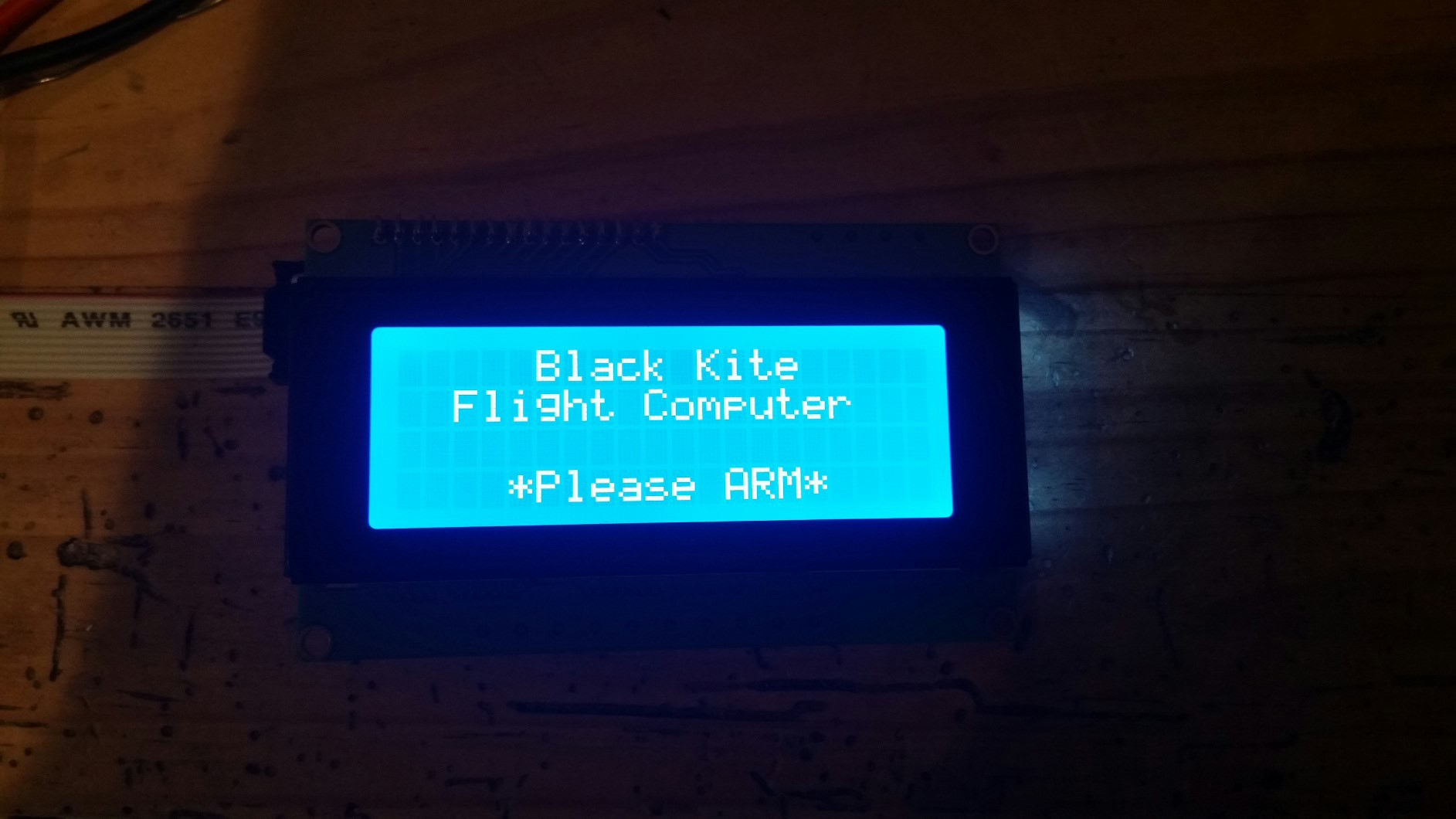
Once started we get a little message saying we are good to go. I now start the flight computer...
![]() We can now intact with the flight computer, sending commands and receiving data. Anything sent back in the serial stream inside brackets gets displayed on the LCD.
We can now intact with the flight computer, sending commands and receiving data. Anything sent back in the serial stream inside brackets gets displayed on the LCD.![]()
For instance, after typing "ma" for maximum altitude request, the LCD gives us the altitude.
Overall I'm very happy. Like I said I'll make a dedicated Hackaday.io project for the wifi serial bridge here soon to keep all the details in one place. I'll be putting it into a project enclosure here before too long also.
Other peripherals such as my thrust measurement stand will be able to interact with the LCD also. Very cool. It will be a useful device. Now any microcontroller with a serial link I can connect an APC220 to and get a remote telnet session and LCD on without any hassle.
-
Serial Stream to 70cm to WiFi to Telnet
02/27/2016 at 02:04 • 0 comments![]()
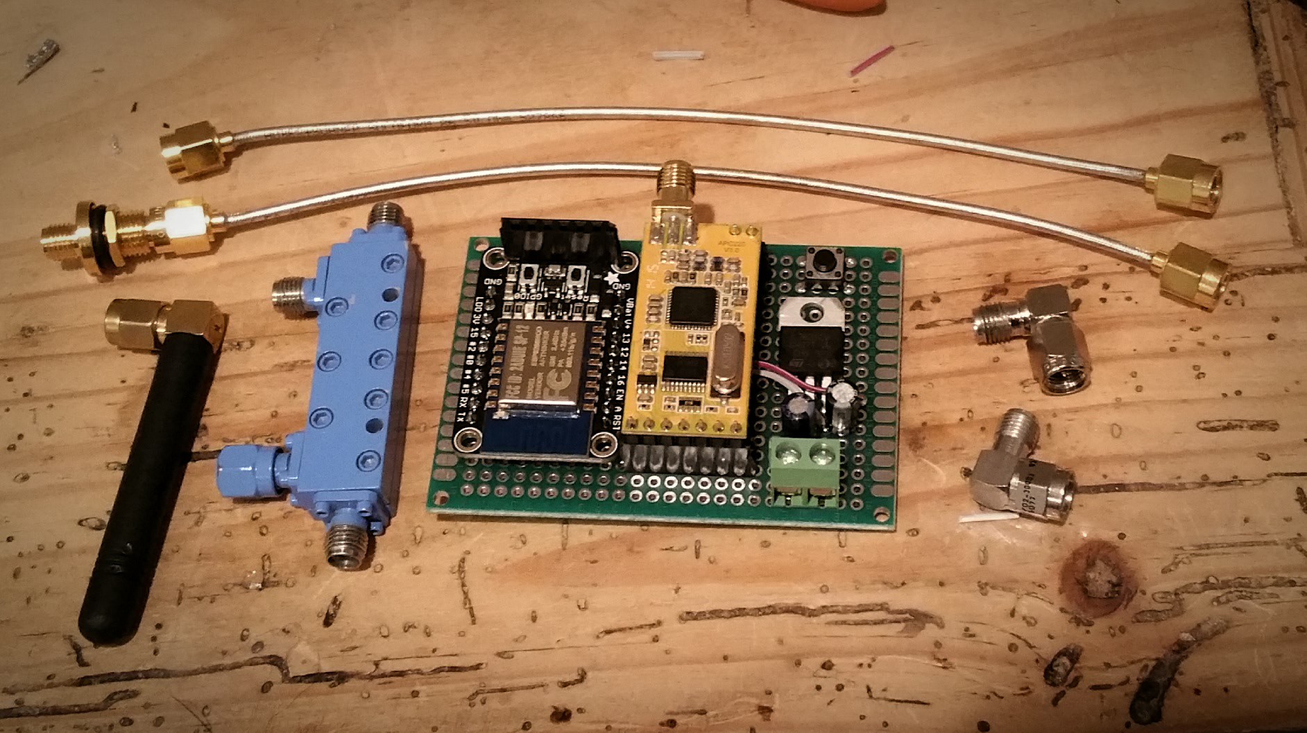
So there is still a little bit left to do here, but let me explain my datapath from before this board was created. The board has a 7805, filtering caps, reset button, APC220, and ESP8266. And a few extra RF goodies laying around it.
The old datapath was as follows:
- Telemetry serial stream generated from altimeter's onboard microcontroller
- Transmitted from the avionics bay through a APC220 70cm transiever
- Received by the 6 element yagi, into my ground station's APC220
- Serial stream piped to the laptop from a translation microcontroller
The new ground station board follows the same path, but extends it to:
- Telemetry serial stream generated from altimeter's onboard microcontroller
- Transmitted from the avionics bay through a APC220 70cm transiever
- Received by the 6 element yagi, into my ground station's APC220
- Serial stream into the ESP8266 WiFi microcontroller
- Cell phone acesses the data stream via a WiFi telnet session
This allows me to not have to haul around the laptop unless I want to, plus I can now control everything from my cellphone. How cool is that?
The next step is to put it all into a real box.
-
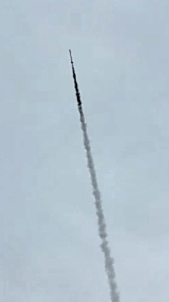
Motor Failure and RF Success
02/21/2016 at 00:30 • 0 comments![]()
![]()
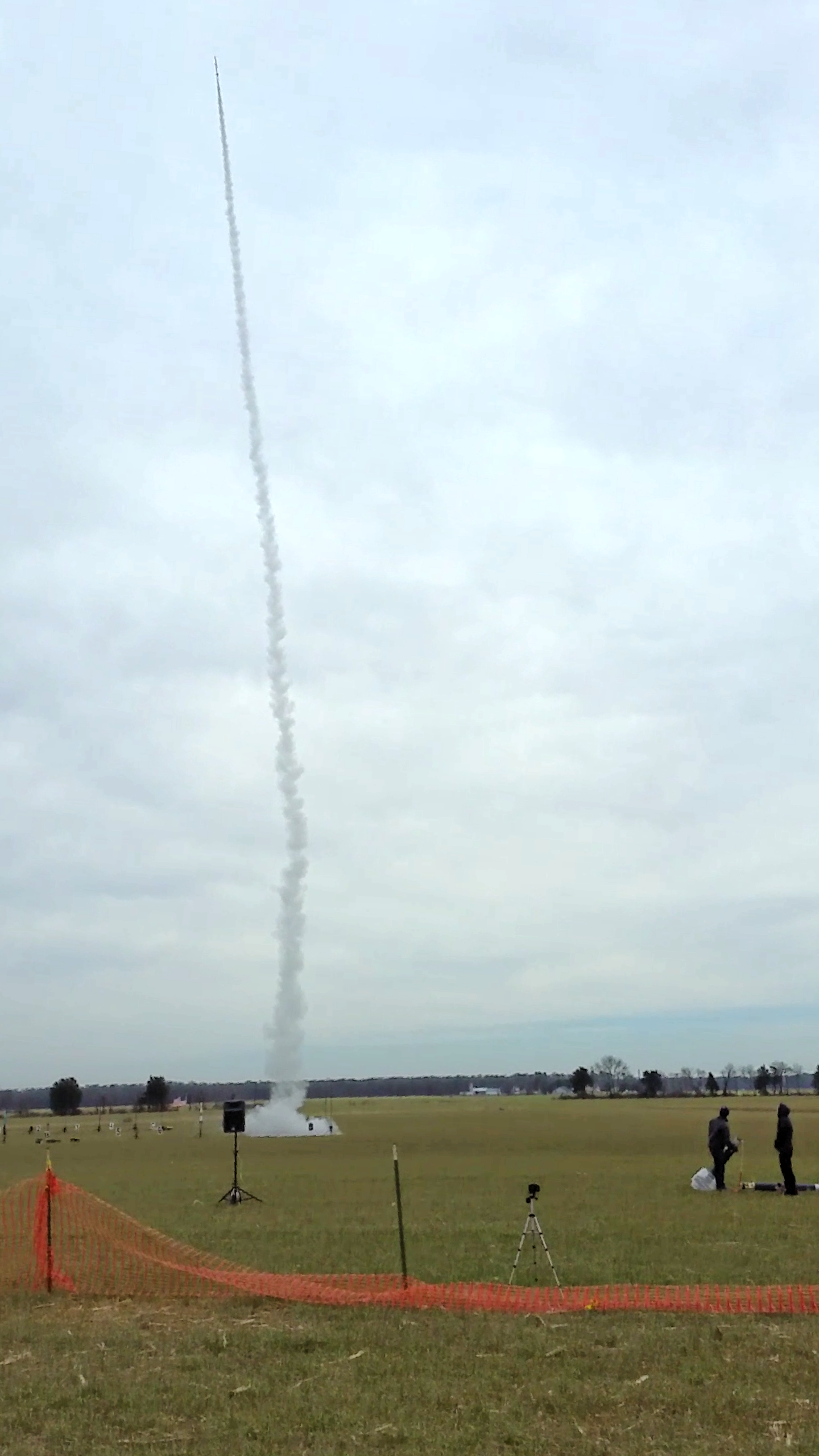
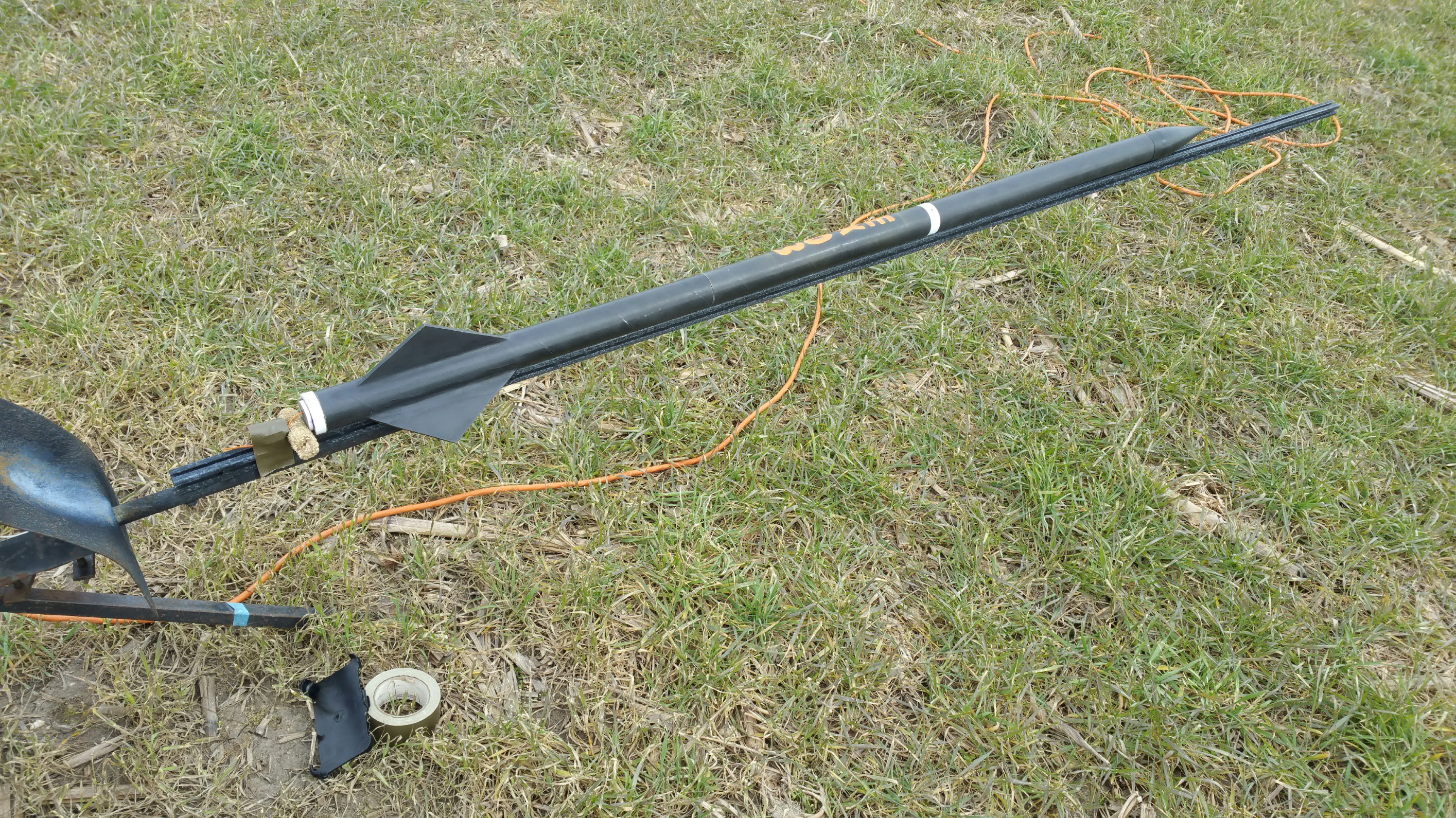
The EX-003 flew today on a I-530 6 grain 1-1/4" motor. This flight was a test for RF transceiver and data path validation.
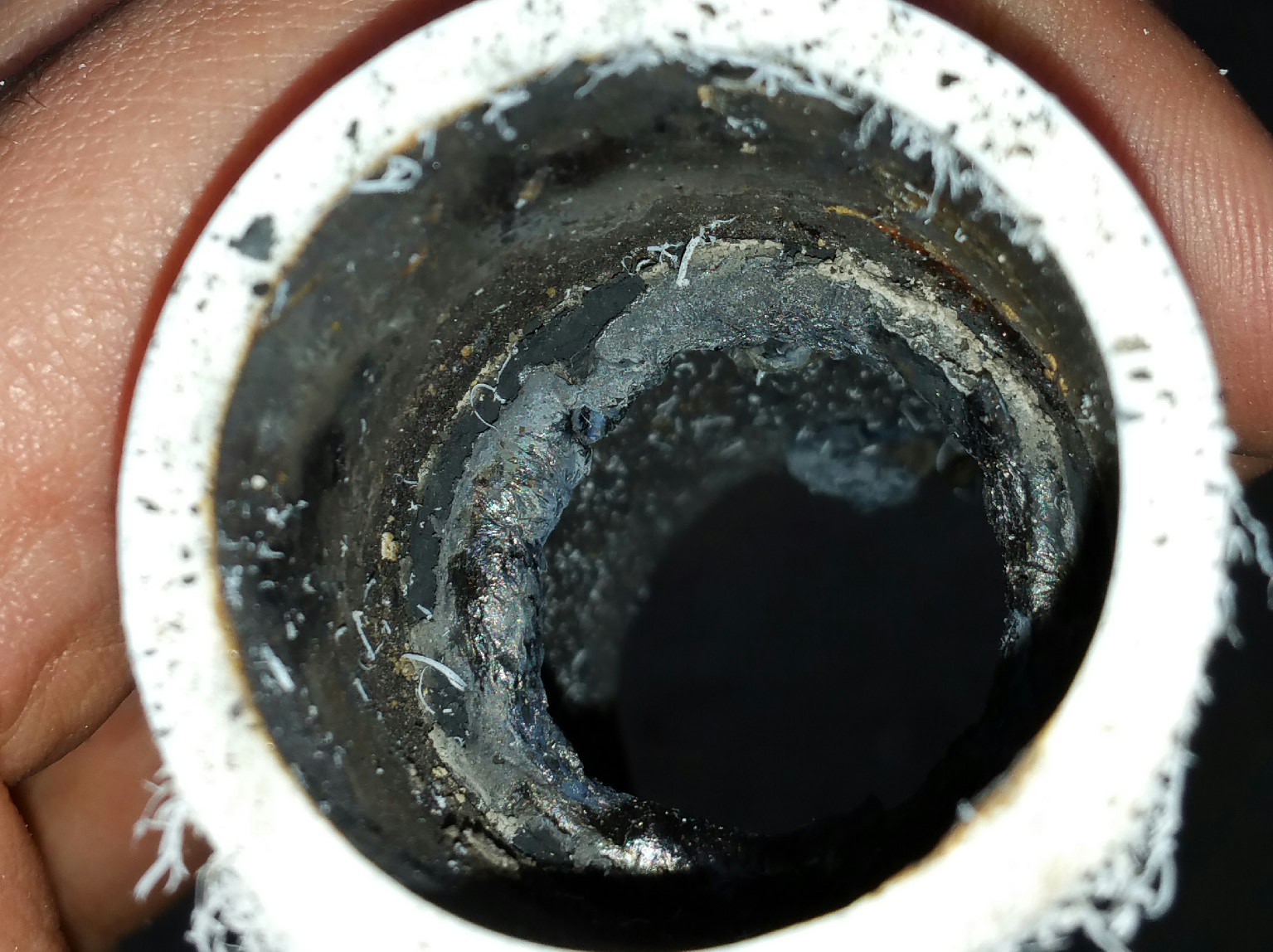
Regrettably the flight was cut short due to a motor failure at around 500ft. Apogee was reached at 730ft. The motor failure was deemed to have been caused by a new propellant grain separation o-ring being used in this iteration of testing which when ejected from the casing became an obstruction to the nozzle causing an over pressure event.
![]()
The picture above shows a sudden darkening of the exhaust plume just before the failure. This is indicative of a large amount of rubber being burned. The likely cause, as stated earlier, is an o-ring partially obstructing the nozzle, drastically reducing the nozzle throat area and causing pressure to climb rapidly.
![]()
Analysis post burn shows an engorged burnt and melted o-ring, certainly capable of obstructing a nozzle.
Following the failure the drogue parachute was ejected at speeds between mach 1.2 and mach 1.3. This high velocity did damage to the drogue, as seen in the next picture.
![]()
The shroud lines were separated from the bottom seam to over half way to the top before the depowering of the parachute halted increased damage. All the gore seams stayed intact.
The drogue took the brunt of the deceleration, and after apogee the main deployed without issue.
On the plus side a limited test of the transceiver was completed and data was sent back via the serial link in real-time to the ground station.
-
39" Cross-form Parachute
02/17/2016 at 00:49 • 0 commentsFinished another parachute, this time a high contrast 39" crossform.
![]()
![]()
![]()
![]()
![]()
-
Chemical Analysis of PNCP #6
02/12/2016 at 20:41 • 0 commentsIn the attempts to alleviate the issues with traditional sucrose based grain brittleness I had switched over to a formulation that used corn-syrup as a humectant and secondary binder. This allowed for the grains to be malleable after casting without the brittleness that plagued early sucrose based propellants.
This post will explain the chemical and physical properties of my new propellant known as PNCP #6 (https://drive.google.com/open?id=1-6AqZODjtBV812eASCuXsPut8QYr2bl7j2L7OMh38Tc).
I will be utilizing a propellant analysis tool known as CHEM [3], which is itself similar to the program known as PEP which is the Propellant Evaluation Program (and its cousins PROPEP and GUIPEP). These programs are chemical equilibrium solvers, solving chemical equations using the “minimization of Gibbs free energy” [1]. Another similar program is the NASA Lewis chemical equilibrium program or CETPC [2].
The program allows you to enter different ingredients in percentages based on mass, and solves the chemical equations to tell you pertinent propellant information. The primary attributes that we are looking at are:
- Density, the weight in lb/in^3
- Temperature, combustion temperature is what helps us with materials engineering
- Gamma, our specific heat ratio, which is the heat capacity per unit of mass
- C-Star, or characteristic velocity, is a figure of thermo chemical merit
- Isp, Specific Impulse is the power of the fuel per unit of mass
The following table will compare :
- Traditional mixture (65% potassium nitrate/35% sucrose)
- Flexfuel mixture (65% potassium nitrate/18% corn syrup/17% sucrose)
- PNCP#6 mixture (65% potassium nitrate/18% corn syrup/8.5% sucrose/8.5% sorbitol) Full readout from CHEM here: https://docs.google.com/document/d/1OPSMKjqOTHAZuHPWtzrh5Q1walCyQBCP0ghi6VthN_8/pub
65/35 65/18/17 65/18/8.5/8.5 Density 0.0682 lb/in^3 .06679 .06626 Temperature 2151 deg F 2192 2131 Gamma 1.1451 1.145 1.1403 C-Star 2752.112 ft/sec 2735.4 ft/sec 2736.38 ft/sec Isp 138.8 139.1 138.3 At this time I cannot simulate the addition of potassium bitartrate or carboxymethyl-cellolose gum into CHEM (it only has a particular subset of chemicals in its database), but these chemicals reduce performance slightly (particularly at the lower levels used), so if we use these design characteristics, we will be simply making a higher safety margin.
We can input these characteristics into BurnSim [4] to model our motors. The only thing we need extra is burn rate information, which experimentally we are using burn rate coefficient of a=.035 and burn rate exponent of n=.35 which has experimentally aligned very well to our composition.
If we use the following grain information: 5 x (1.3”OD, 2.5”L, 0.5625”ID), 1 x (1.3”OD, 4”L, 0.5625”) with a nozzle of .4375” with 5X expansion, we get the following motor:
- Initial Kn: 280
- Max Kn: 335
- Max Pc: 639PSI
- Volume Loading: 81.3%
- Burn Time: 1.13 sec
- Propellant Length: 16.5”
- Propellant Mass: 1.189lb
- Total Impulse: 592NS
- Motor Class: 85% I-524
- Delivered ISP: 112 sec
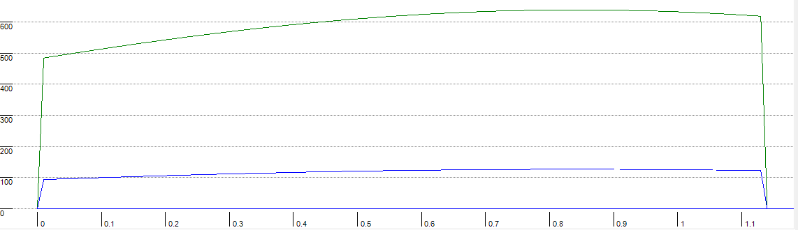
And this is the thrust curve graph:
![]()
Overall this is a very nice, strong, slightly progressive motor capable of lofting a 5 lb rocket up to a mile or so. Not so shabby for sugar fuel!
[1] http://www.nakka-rocketry.net/th_prope.html
[2] http://ntrs.nasa.gov/archive/nasa/casi.ntrs.nasa.gov/19940028442.pdf
-
Aeroelastic Fin Flutter Calculation
02/03/2016 at 04:26 • 0 commentsWhat is aeroelastic fin flutter? Simply put, fin flutter is an effect where the physical properties of the fin material will cause an amplification feedback loop that will eventually cause large oscillations and physical failure of the fin medium. Or by textbook:
“A dynamic instability associated with the interaction of aerodynamic, elastic and inertial forces.” [1]
or
"Flutter of an elastic body is a self-excited vibration of that body while immersed in fluid flow. In the case of a rocket, flutter is associated with the aero-elastic characteristics of the fin/body combination while flying through the atmosphere. Flutter is typically the coupled motion of fin twist (torsion), fin plunge (bending) and possibly the rigid and/or flexible motions of the rocket body." [2]
There are a few methods of calculation differing in complexity and relying more and more on specific physical properties that are exactly defined. Much of what we work with we can give estimations on, but variances of up to 10-20% can be expected. Therefor it is recommended that a high safety margin by utilized to minimize the risk of failure.
We will be using the Flutter Boundary Equation based on a technical report on NASA's research server [3].
The equation is as follows [1] [3]:
We will step by step go through the calculations necessary, please see further down the post or look at [1] and [3] for more details on this formula, but know that :
- G = materials shear modulus (strength of material in PSI)
- P = Atmospheric pressure, see [4] (in PSI)
We will calculate the fin flutter for my last rocket which utilized a fin that was:
- Root chord: 9" (length of fin on body)
- Sweep: 5" (distance of tip of fin from start of fin)
- Tip chord: 0" (came to a point at end of fin)
- Thickness: 0.25"
- Semi-span: 3" (distance furthest from the rocket body)
- Shear Modulus: 2,020,000 PSI (derived from reference from Finsim software [5])
- Altitude: 2,000ft (Altitude of max velocity, not apogee of rocket)
We can now calculate the fin surface area:
The fin aspect ratio:
The ratio of tip to root chord:
Temperature at altitude (see [4]):
Speed of sound at altitude:
To make calculations a bit easier we will now brake apart the original equation into three parts. (NACA TN 4197, EQ 18):
The actual flutter velocity will now be:
We can now convert this to mach by:
These stubby little fins are actually quite strong due to the limiting sub span length. If we increase these fins from 3" to 4" we get the following:
If we add a 25% safety margin we reduce this down to mach 2.496.
It needs to be taken into consideration that materials properties are much more exact in metals, less so in composites, and even less so in wood. This variance can easily cause huge discrepancies.
One can also automatically calculate these values utilizing more exact computational fluid dynamic simulations on software known as "Finsim" [5] I urge those interested to sign up for the software and enjoy it.
Any questions are welcome, hope this illuminated some of the math in rocketry for you.
[1] https://www.apogeerockets.com/education/downloads/Newsletter291.pdf
[2] https://drive.google.com/file/d/0ByUEkb0cIAHncUN4ejhEZWtsRWc/view
[3] - http://ntrs.nasa.gov/archive/nasa/casi.ntrs.nasa.gov/19930085030.pdf
[4] http://www.grc.nasa.gov/WWW/K-12/airplane/atmos.html
[5] http://www.aerorocket.com/finsim.html
-
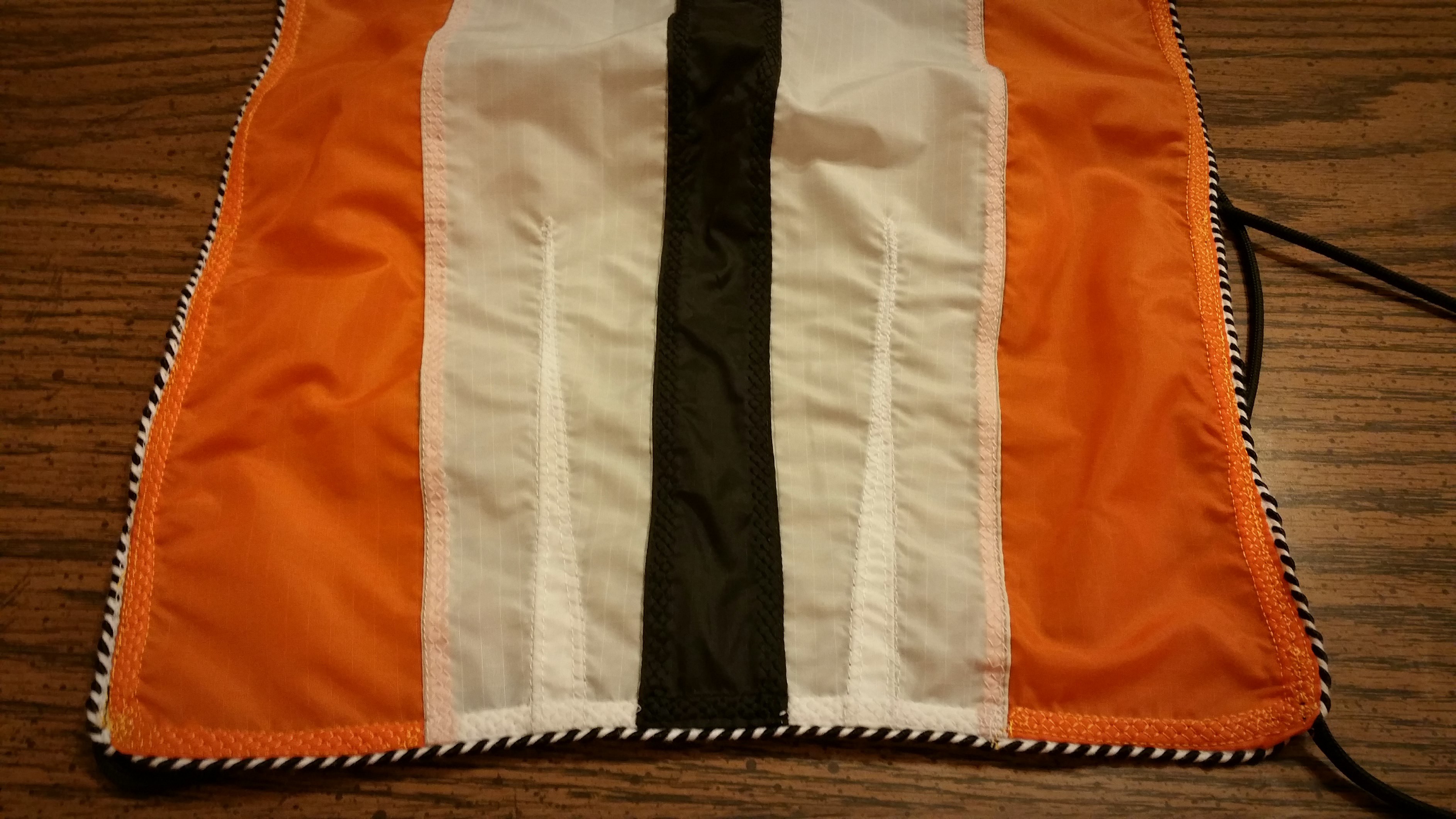
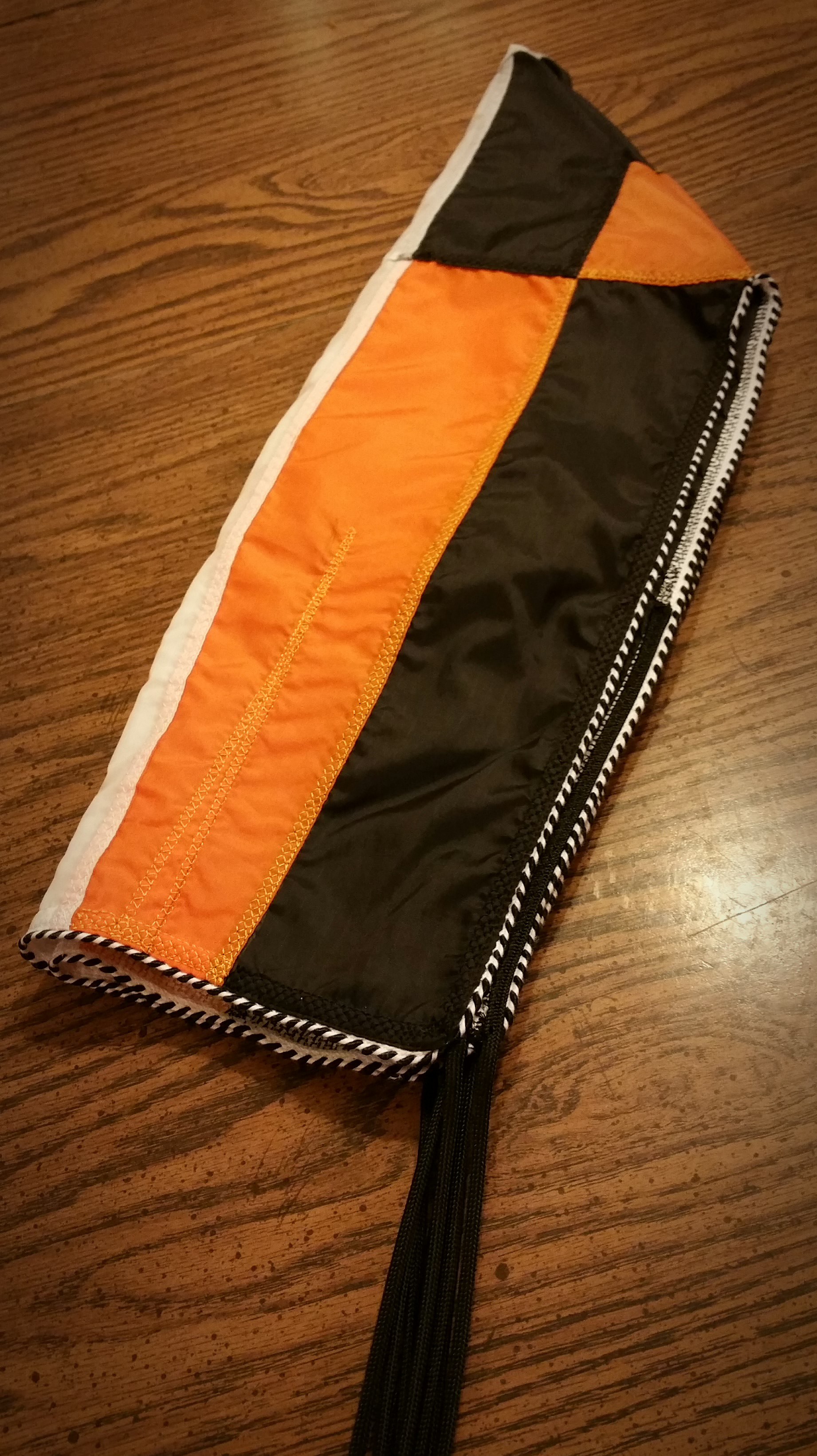
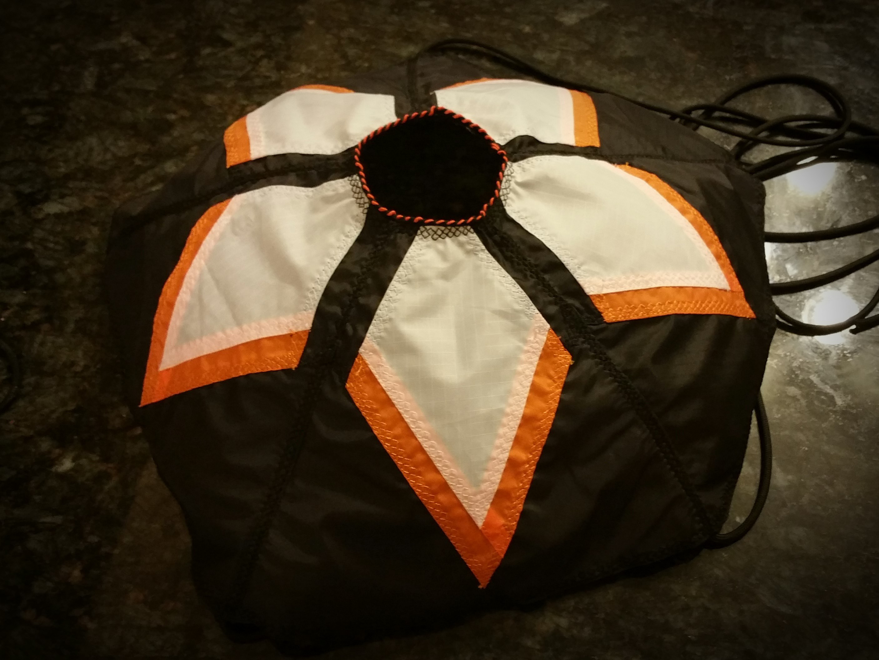
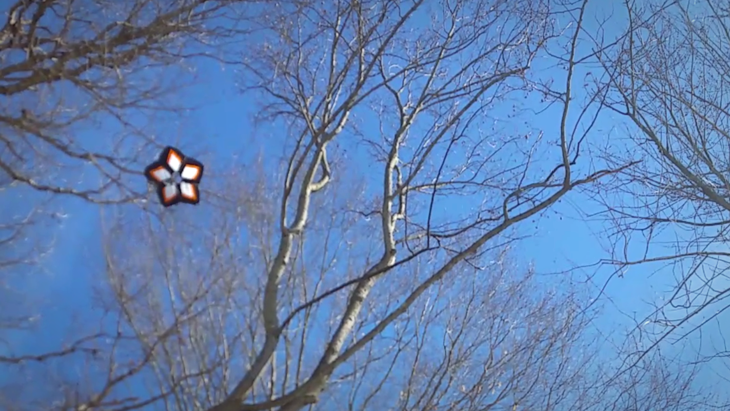
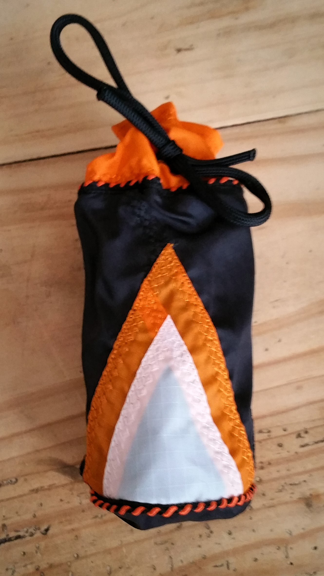
Star Drogue
01/31/2016 at 20:42 • 0 commentsThis last week we suffered through a blizzard, so I took the time to create another color matching drogue parachute.
It is a 15", 5 gore, 25% hemispherical parachute with a 2" spill hole.
![]()
The pattern utilizes black orange and white in a star pattern.
![]()
![]()
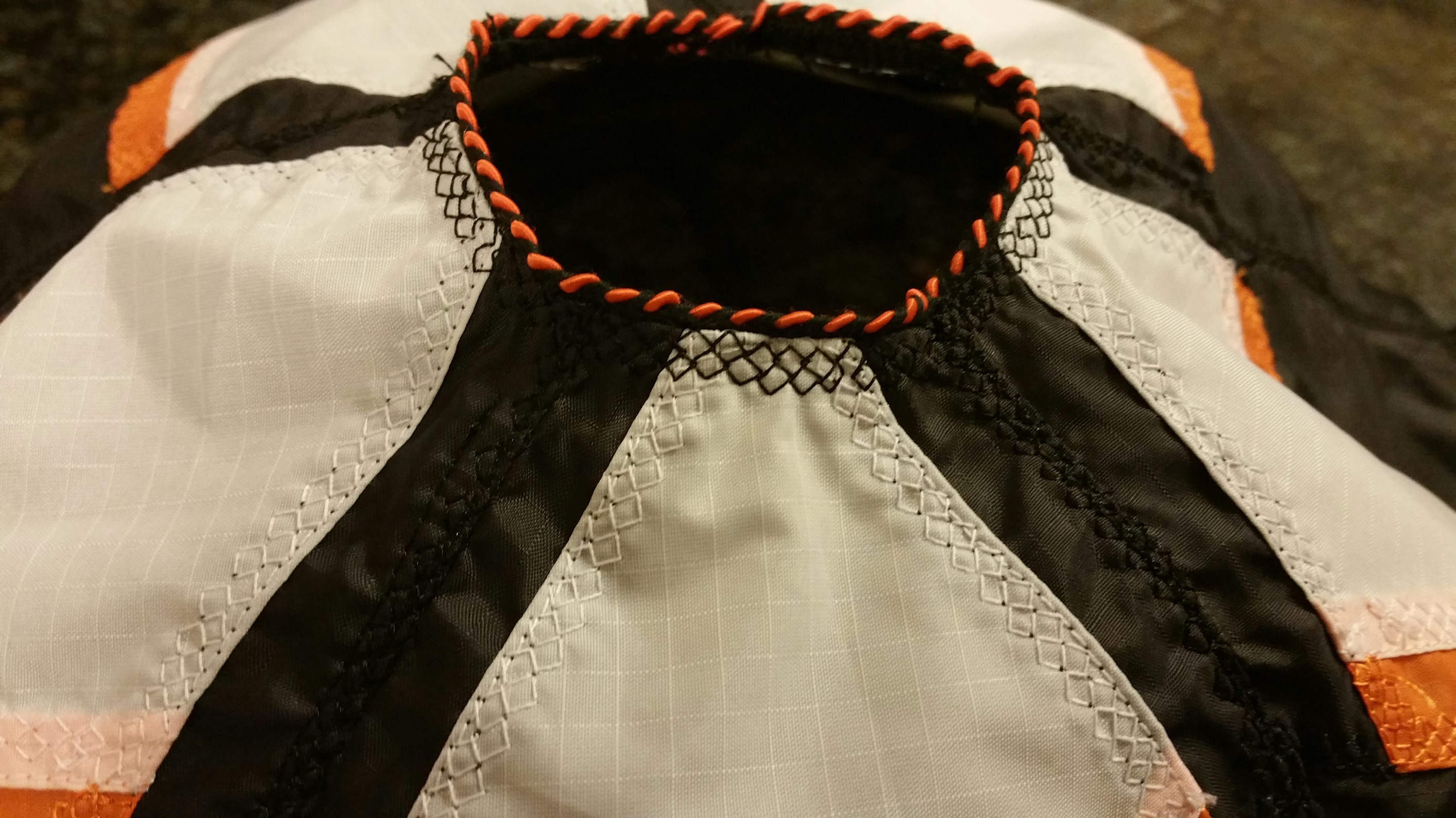
With decorative piping and lots of sewing.... All the seams were competed with full French fell seams, with a hatched stretch stitch to hold it all together.
![]()
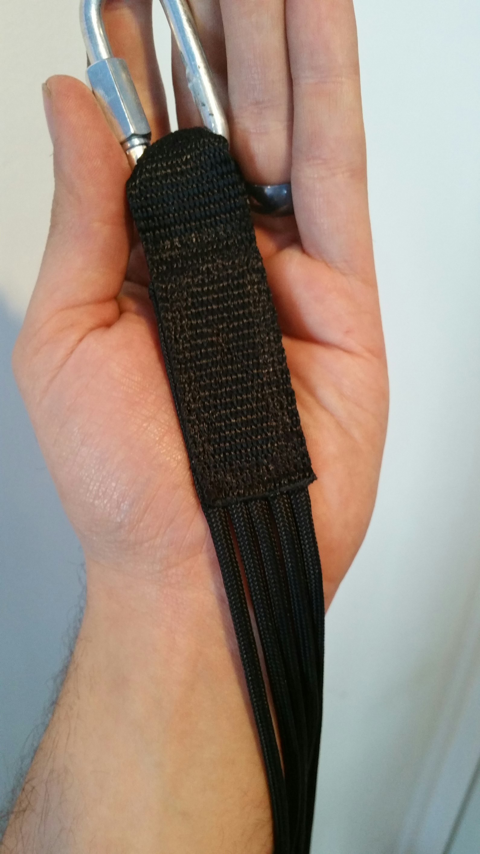
Termination of the shroud lines was by sewing onto nylon strapping with a quick link.
![]()
In the air it came out quite nicely.
![]()
And here's the long term storage bag.
-
Ignition Testing
01/19/2016 at 02:31 • 0 commentsOne of the issues I've dealt with most of my motor testing was a relatively slow ignition time. This was caused by the necessary build up in pressure before enough hot gass propagated through the case and the motor achieved full ignition.
To enable faster ignition I needed both an ignition source and pressure source. To that end I've built a new igniter:
It successfully gives me that instant on ignition that had been eluding me.
Here's an example of an old finocyl bored grain being ignited with the previous method:
High Power Experimental Rocket Platform
Experimental high power rocket with active stabilization, live telemetry, autonomous GPS guided recovery and HD video

 We can now intact with the flight computer, sending commands and receiving data. Anything sent back in the serial stream inside brackets gets displayed on the LCD.