J. M. Hopkins
-
Motor Success
01/18/2016 at 01:00 • 0 comments![]()
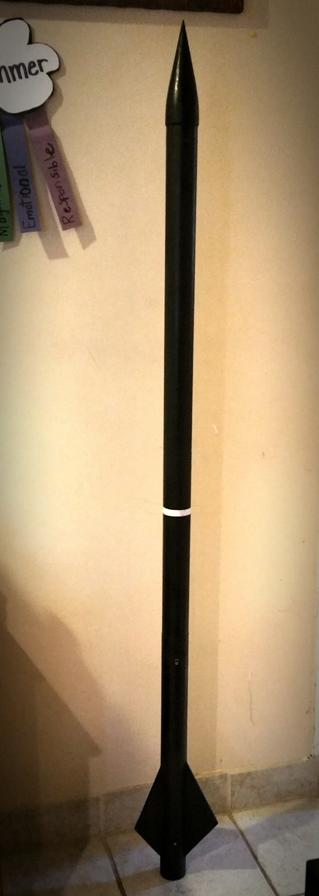
Today I successfully static tested and flight tested my new 6 grain motor utilizing the new epoxy construction method. I feel comfortable with this design and will use it as the test bed for my payload lofting rocket for autonomous recovery.
![]()
![]()
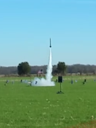
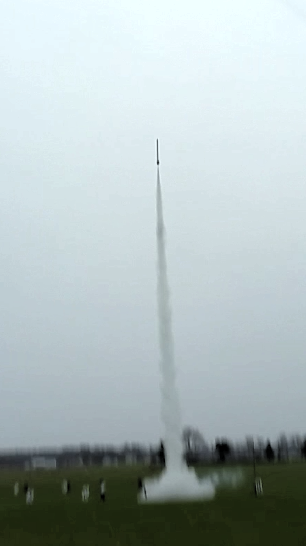
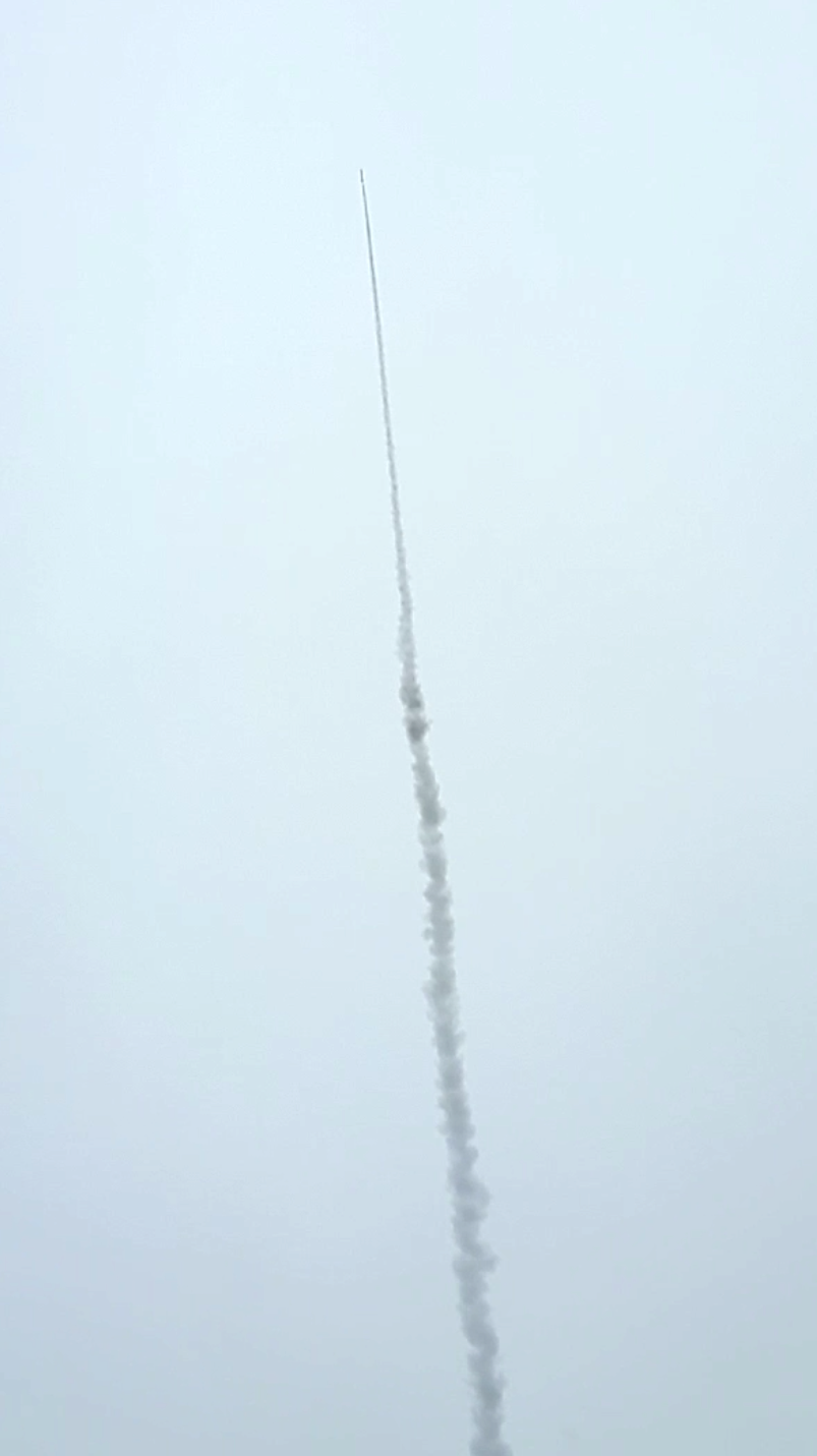
You can see liftoff was nice and straight.
![]()
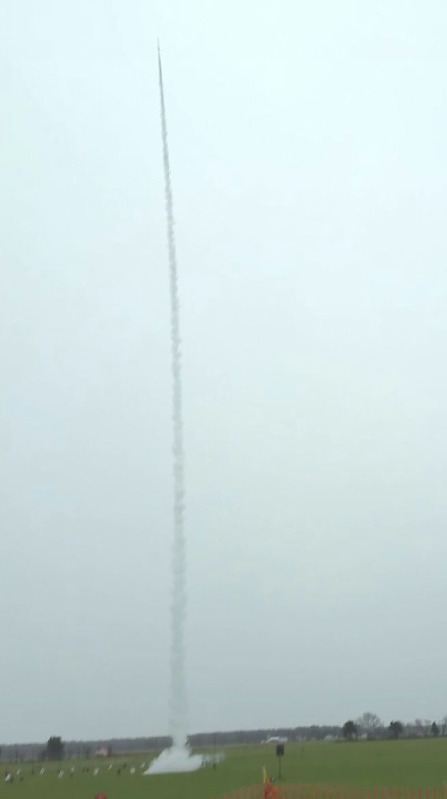
And the full burn was strong and slightly progressive. Overall I'm very impressed with the design.
Motor design specifics are as follows:
- I-530 designation, 1.2 second burn
- 1-1/4" PVC casing
- 5 x 2.5" grains, 0.652" bore
- 1 x 4" grain, 0.652" bore
- 7/16" throat, 4.2x expansion
- KN progressive between 300 and 350
- Posterboard inhibitor
- Plastic epoxy construction
-
Cross Form Parachute and More
01/14/2016 at 22:46 • 0 commentsThis weekend is my next club rocket launch. After last month's motor failure I have built a new rocket and several parachutes to accommodate the lighter airframe.
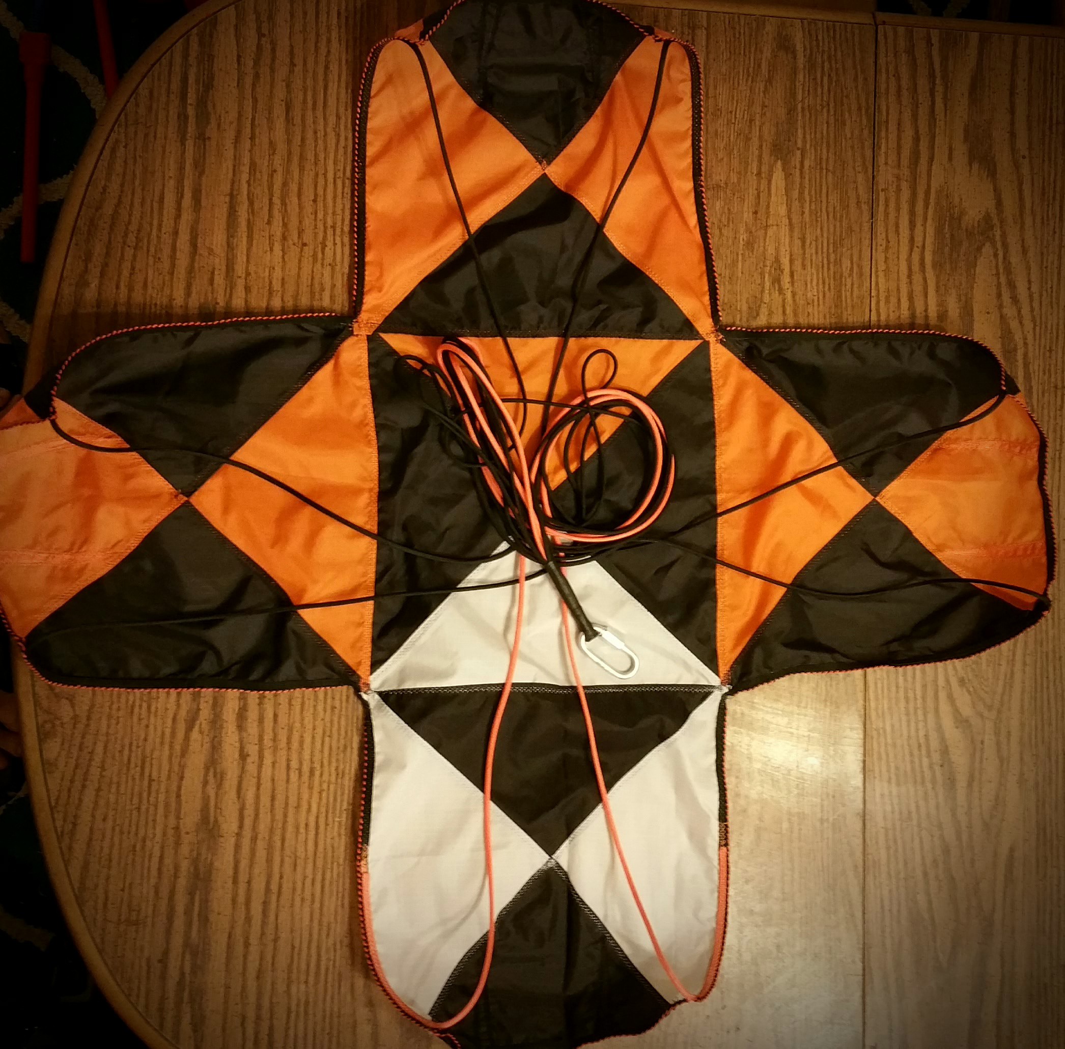
![]()
You can see from the above picture the high contrast color scheme with asymmetric coloring for rotation analysis.
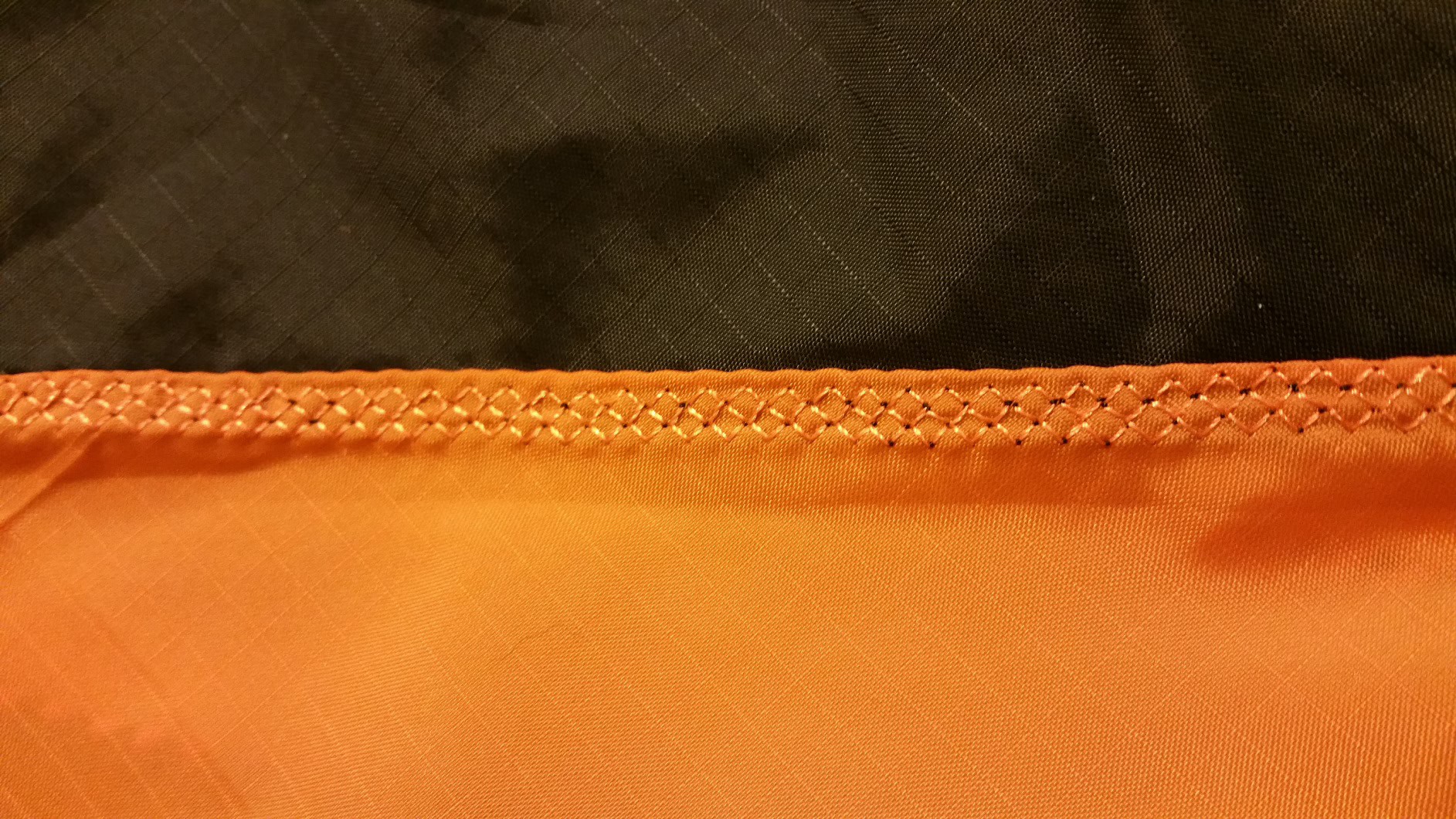
![]()
The seams are full French fell seams with aggressive hatched over stitch.
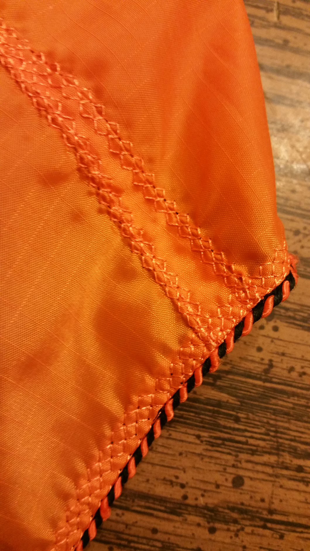
![]()
Contrary to normal cross form parachutes this design utilizes two darts per arm, giving a slight curvature and hopefully slightly higher Cd when compared to standard designs.
This parachute will be deployed at 1,000 feet AGL and the drogue from last post will be at apogee.
The new motors that will be flown are actually larger than last month, but will be operating at a lower pressure, even though having a higher mass flux. They are nearly 20" long, utilizing nearly 1-1/2lbs of fuel.
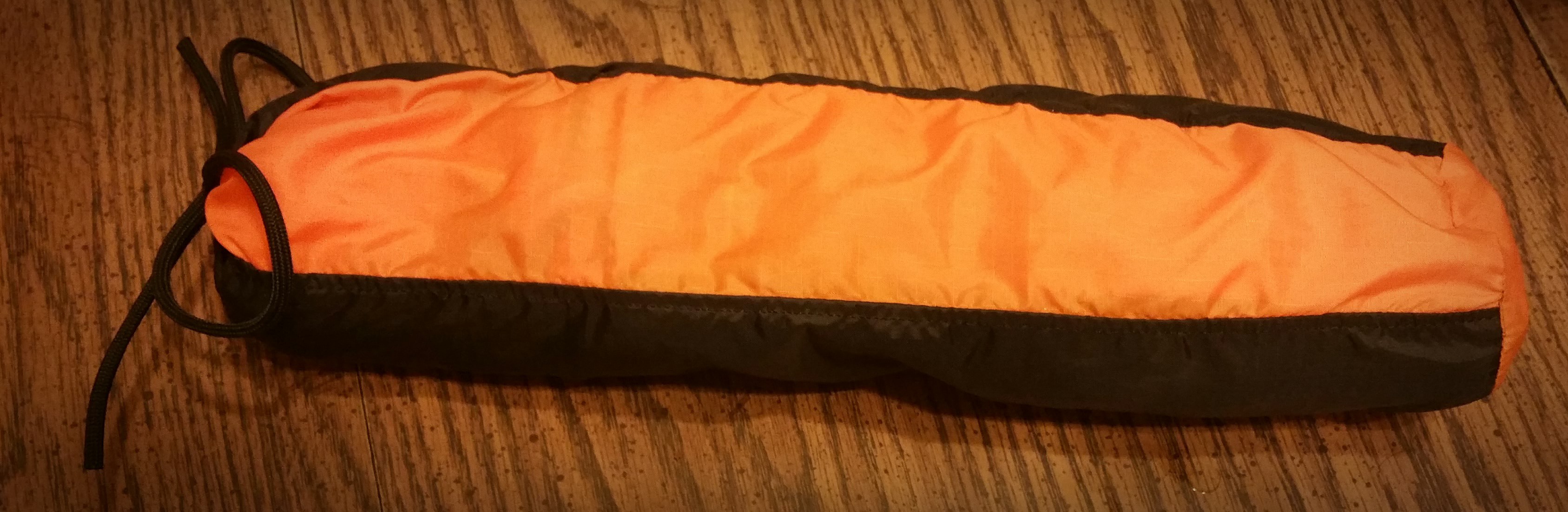
![]() The obligatory storage case turned out quite well, with room for the drogue on top.
The obligatory storage case turned out quite well, with room for the drogue on top.The new airframe will be painted tonight and the AV bay and final prep work will be done tomorrow.
Using a mock up I've successfully tested my ejection charges as well, so all in all the program is getting back on track!
There might be a Mobius action cam running on this next rocket, so that should be interesting as well.
-
Extra Strength Drogue Parachute
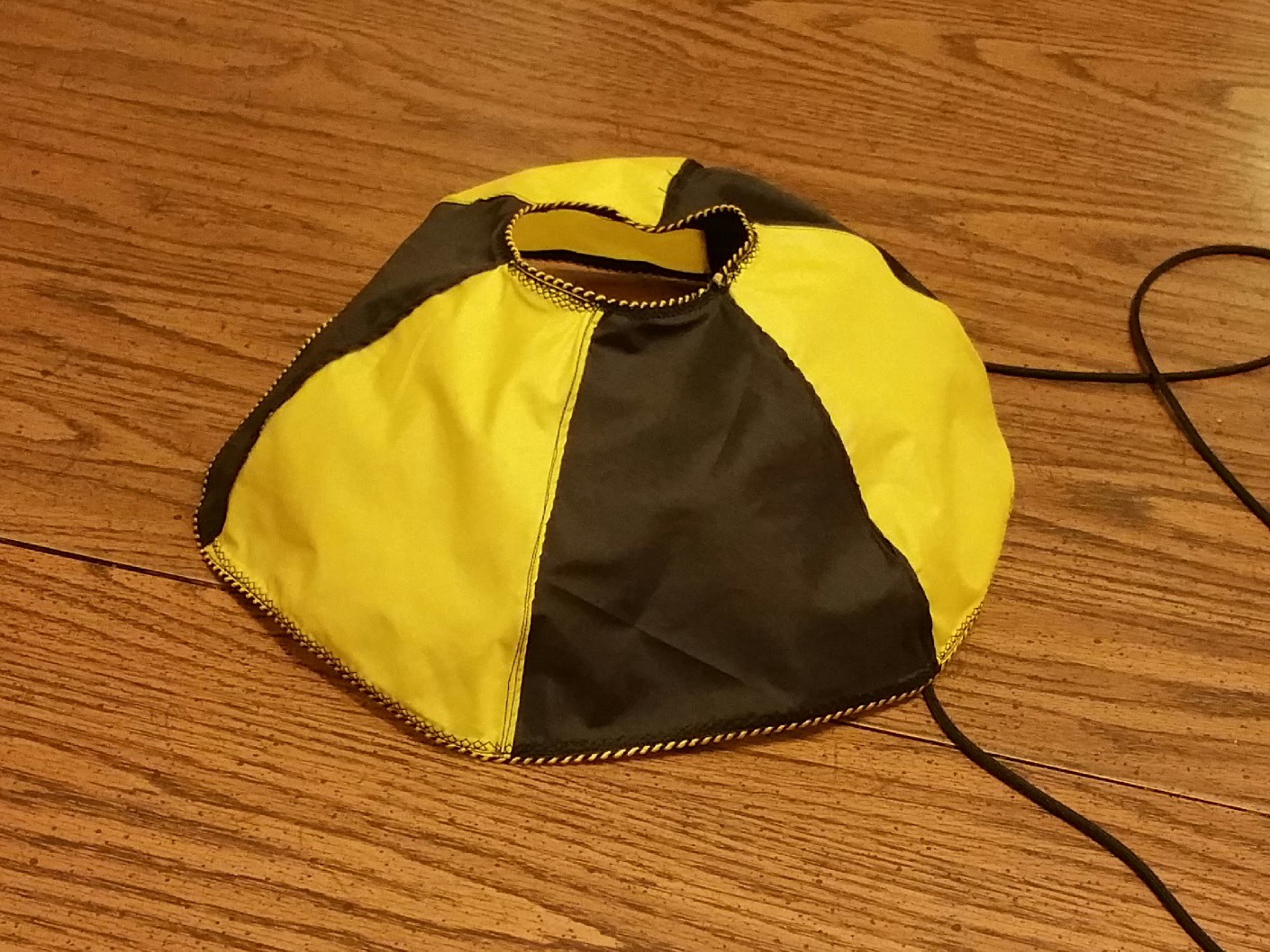
01/02/2016 at 21:48 • 0 commentsThis drogue/pilot parachute is a 14" 6 gore 35% hemispherical parachute with a 4" spill hole. It is constructed to withstand high speed deployments, hence the larger spill hole and extra strength seams.
![]() Each gore is cut out with a soldering iron on the bias (45° to the fabric grain) from 1.7oz ripstop nylon. Black and yellow was chosen for the color visibility reasons.
Each gore is cut out with a soldering iron on the bias (45° to the fabric grain) from 1.7oz ripstop nylon. Black and yellow was chosen for the color visibility reasons.
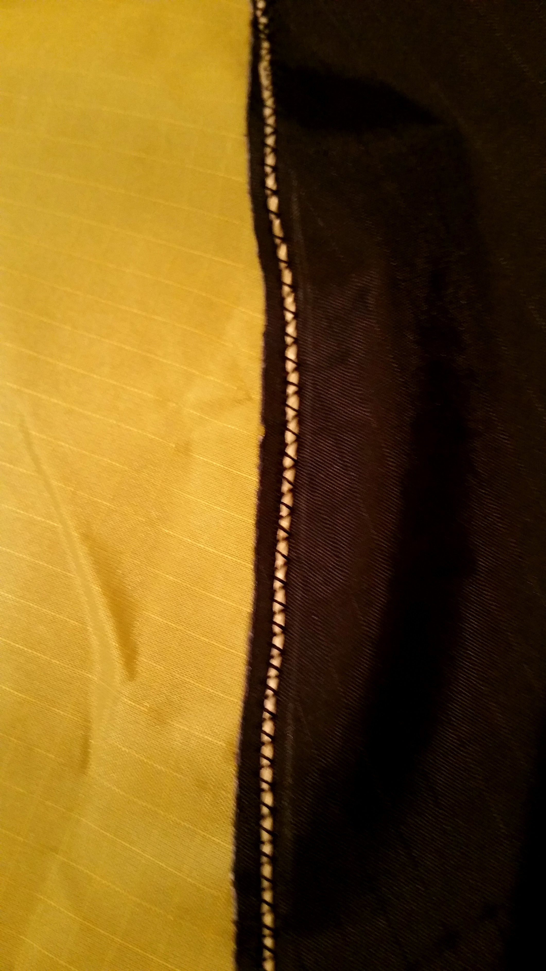
Each seam is a flat fell seam with a stand of 100lb test Kevlar line in the middle.![]()
![]()
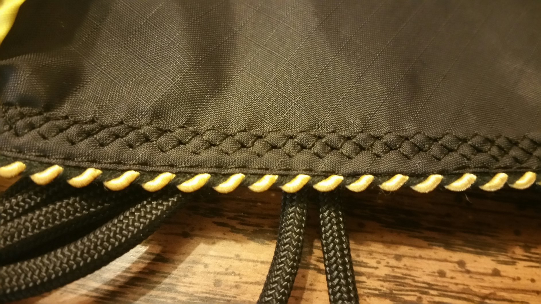
Each seam is finished with a robust hatched stitch and the edges trimmed with color matched piping![]()
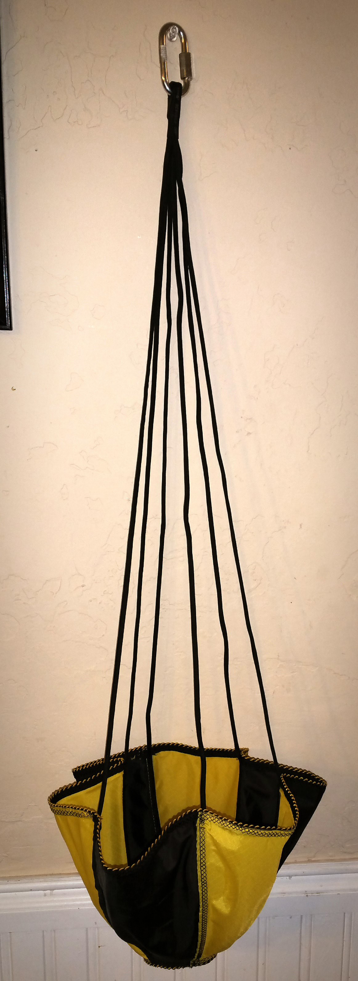
550 paracord is used as shroud lines, and are attached full length from spill hole to lower edge.![]()
![]()
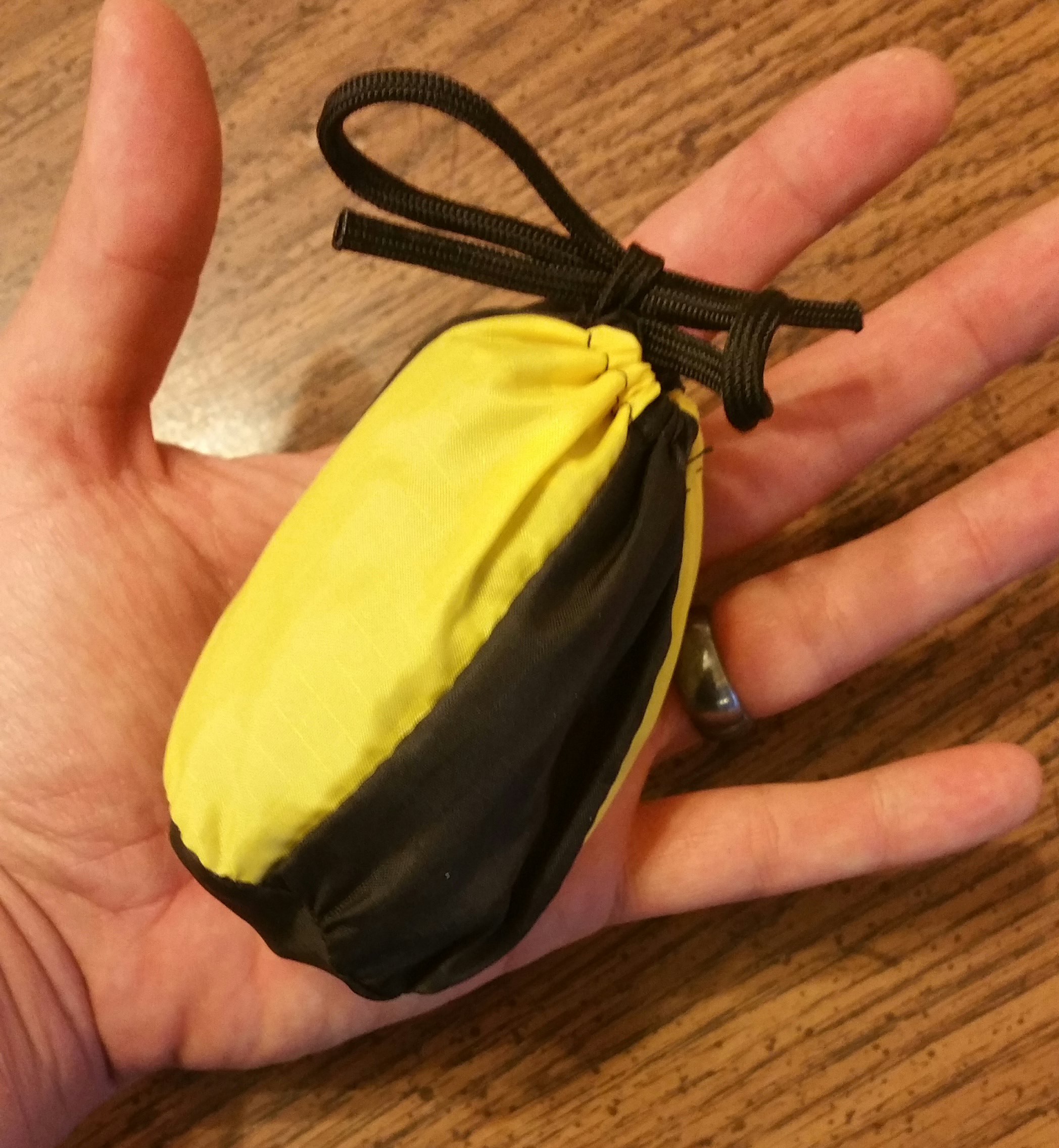
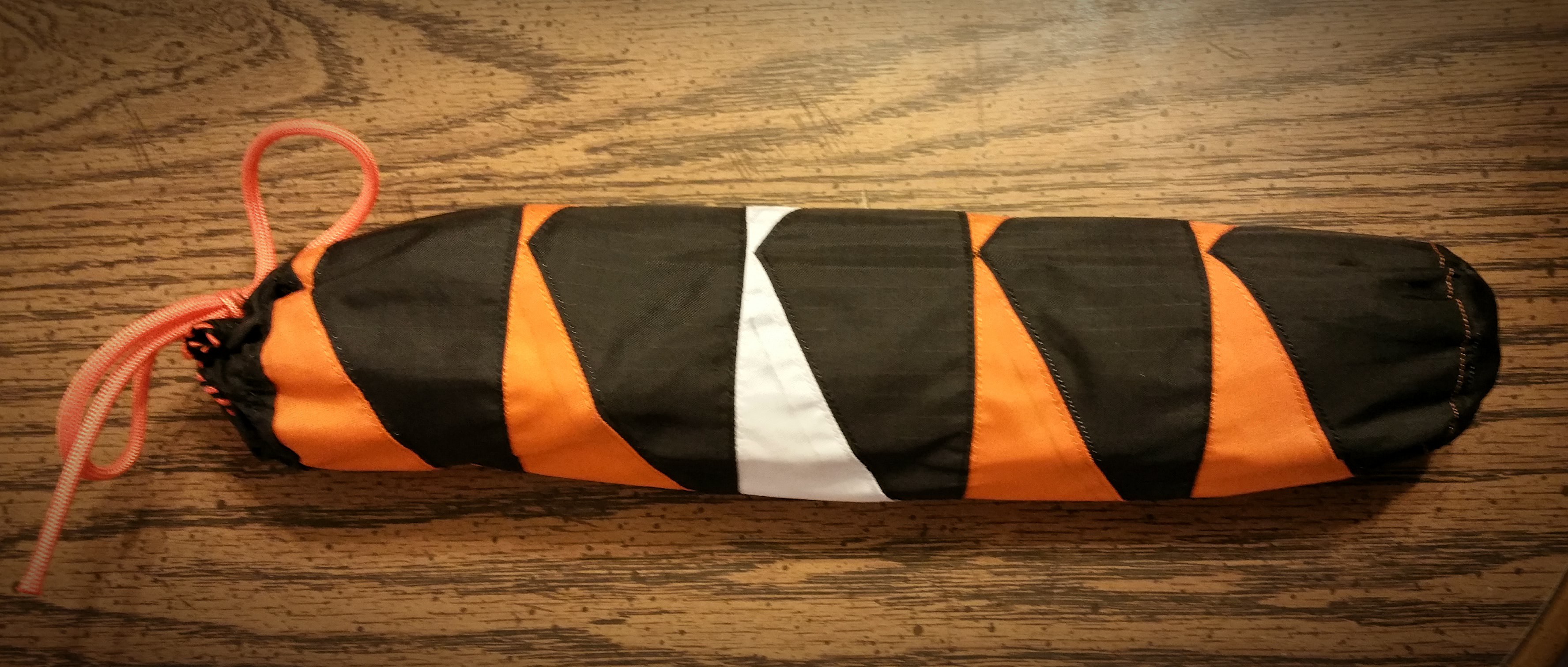
And an obligatory carrying/storage case was made.
![]()
Here's the storage bag for the backup parachute, it has room for the drogue on top.
-
Motor Failure and Parafoil Testing
12/20/2015 at 21:02 • 0 comments![]()
![]()
![]()
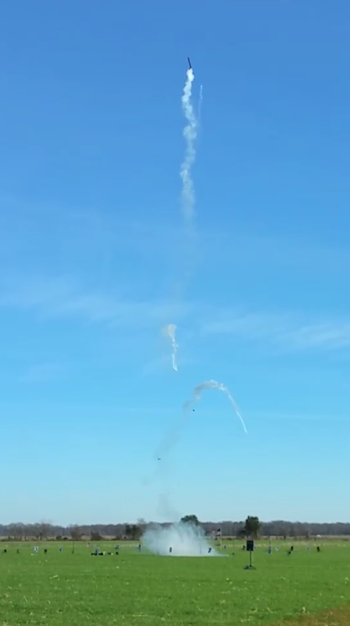
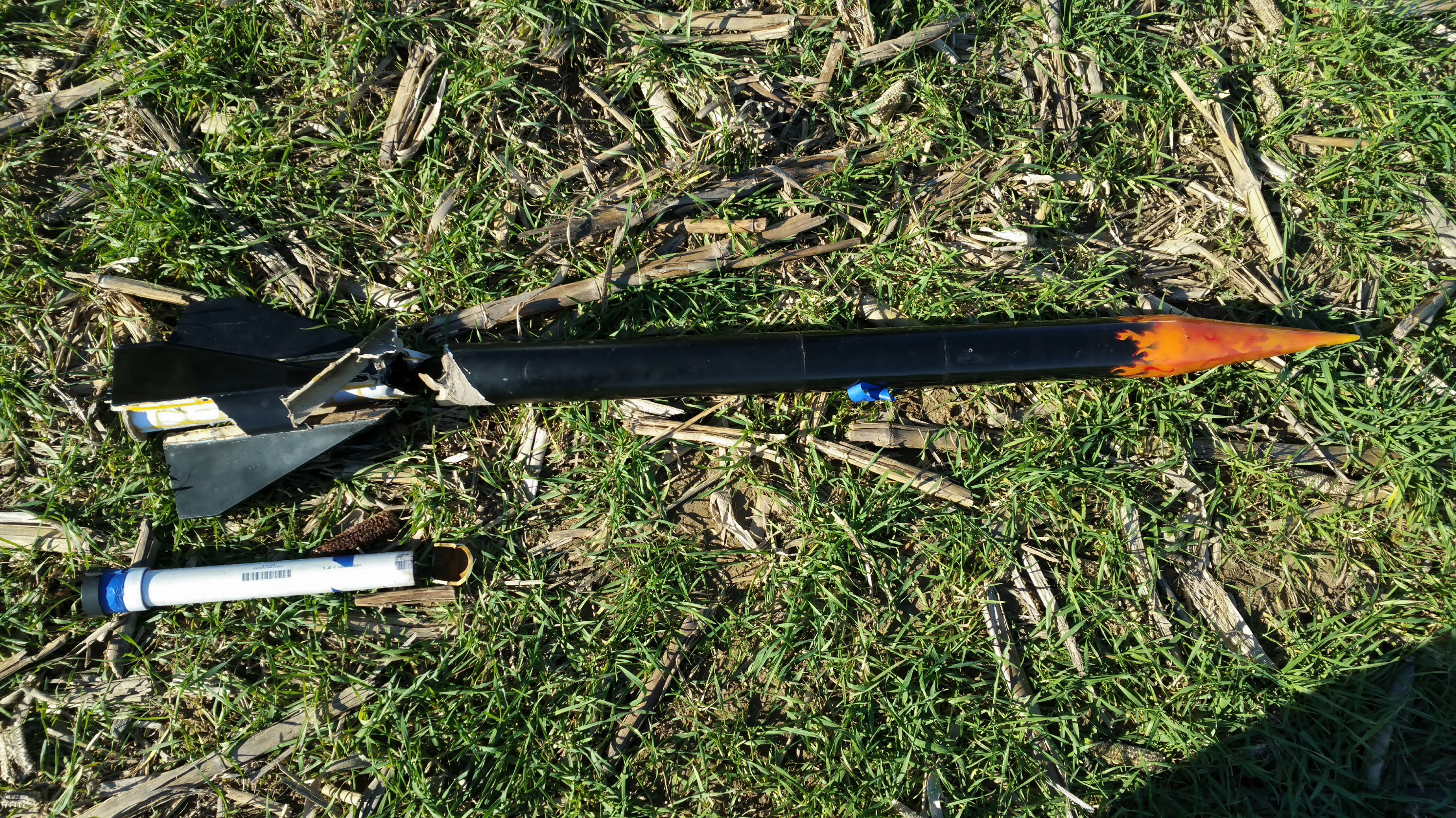
Today the project suffered a setback in the form of a catastrophic motor failure shortly into flight that resulted in rapid disassembly of the fin can.
The motor forward bulkhead failed at the glue bond line. Likely due to ineffective bonding. This was the first failure of this type in some 35 static tests, and not expected to happen again.
To limit the chance of a failure, multiple motors of the same design were constructed and tested prior to launch. To limit failure in the future a better bonding agent will be utilized.
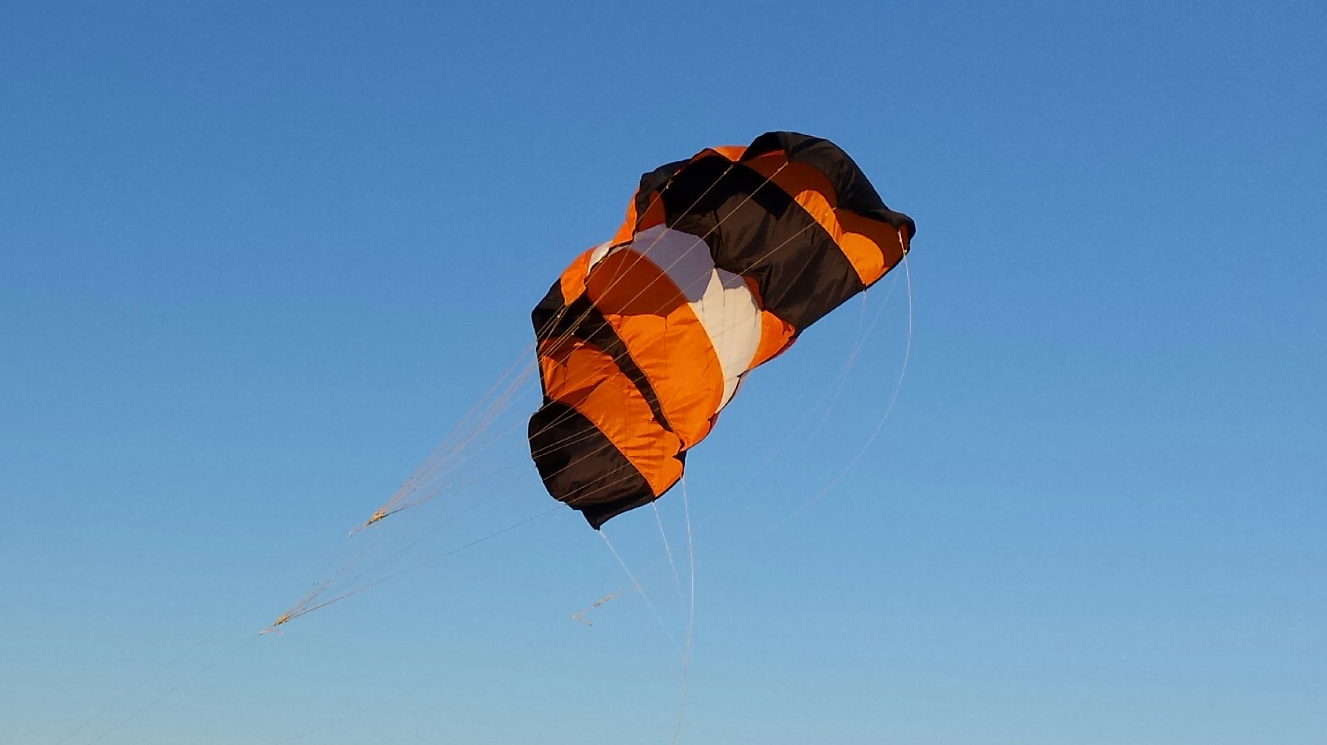
As a plus I did successfully test my single skin parafoil at the beach. I'm going to be doing some additional bridal adjustments, but so far I'm pleased.
![]()
Looks like I'll be able to get 15-20 mph of wind penetration with a wing loading of 6-8lbs. Quite acceptable.
![]()
-
Balance Scale and Ascorbic Acid Recrystalization
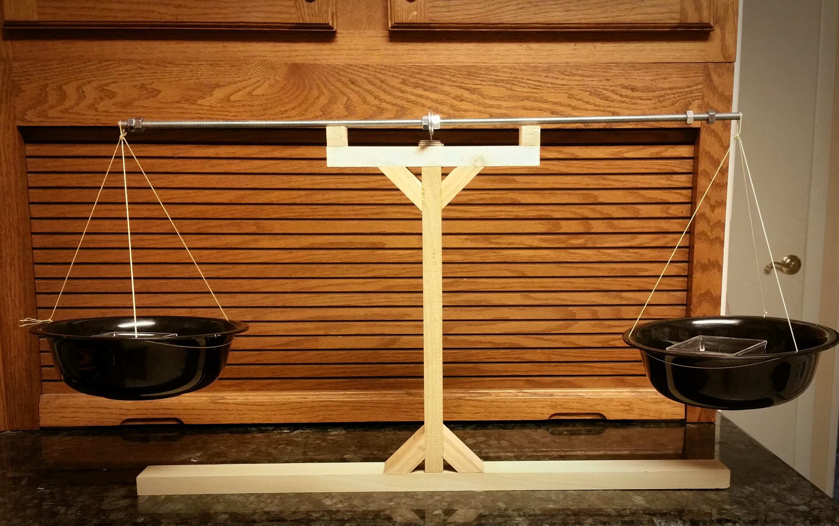
11/30/2015 at 04:11 • 0 commentsDue to the delay in my test launch to next month I have made a balance scale and recrystalized 100g of ascorbic acid from vitamin C supplements.
![]()
I'm going to be doing some more development in my weight containers, but the scale itself is accurate to at least 0.05g, far more accurate than my digital scale. Very useful for measuring ingredients in the batch size of 10g or less.
![]()
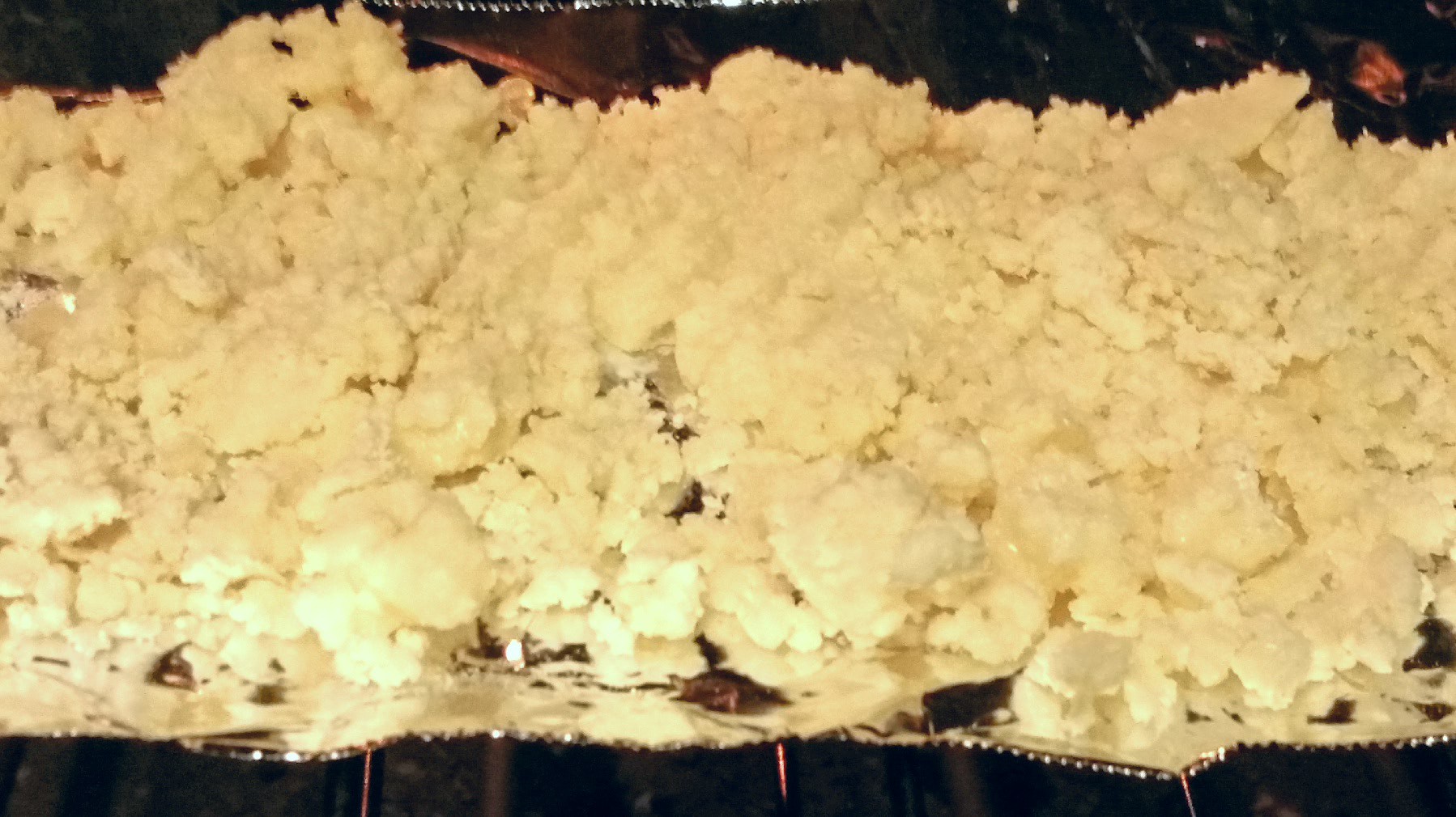
To recrystalyze ascorbic acid from vitamin C supplements, the extra cellulose fiber (making up to 15% of a 1000mg supplement) must be removed.
This is accomplished through dissolving the supplements into water, filtering the solution through a paper towel (three times), and then reducing the solution with heat on the stove to a wet paste. This paste is then transferred to aluminum foil and dried in an oven at 200°F for one hour.
After drying the chunks are ground to a powder in a coffee grinder to a very fine consistency and stored for future use in a Ziploc bag. The final color is an off white light tannish yellow.
![]()
-
Launch Delayed
11/25/2015 at 21:06 • 0 commentsUnfortunately the launch window had higher winds than I was comfortable with. I will be launching at next month's club launch in December.
In the mean time I will continue some other project developments. Stay tuned!
-
Launch Date and Fuel Grains
11/12/2015 at 17:19 • 0 commentsIf the weather holds true the first launch of my rocket will be on 21 November at the MDRA launch in Maryland. It will test numerous things:
- Rocket motors under thrust
- Construction techniques of the rocket
- Flight computer and tracking
To limit ejection failure I'll be utilizing a secondary altimeter.
I'll be testing a few new motor concepts (progressive single grain, BATES grain, and finocyl grains) and deciding which motor I want to fly with after a few static tests.
Here's the sample of the fuel grains that are going to be in a BATES configuration:
![]()
![]()
And the cast nozzles waiting to be used.
-
Static Tests
10/11/2015 at 01:23 • 0 comments![]()
![]()
I was able to test 4 motors with my new wireless rocket motor analyzer at the monthly MDRA club launch. I am really impressed with the data obtained as well as my aggressive burn 1" diameter motor. Great stuff.
-
Digital Static Thrust Measuring
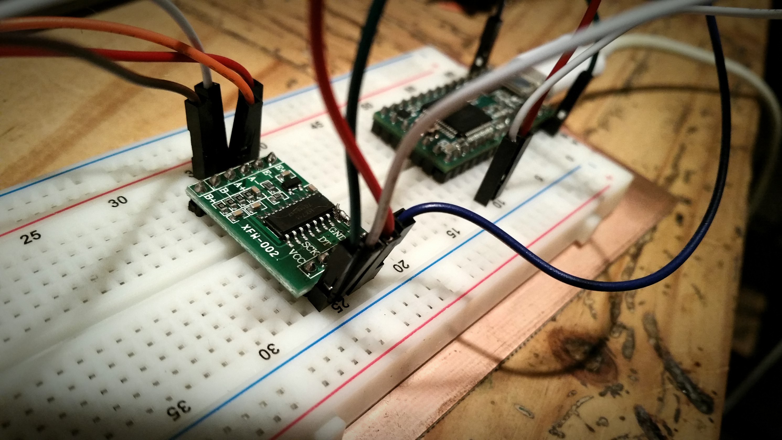
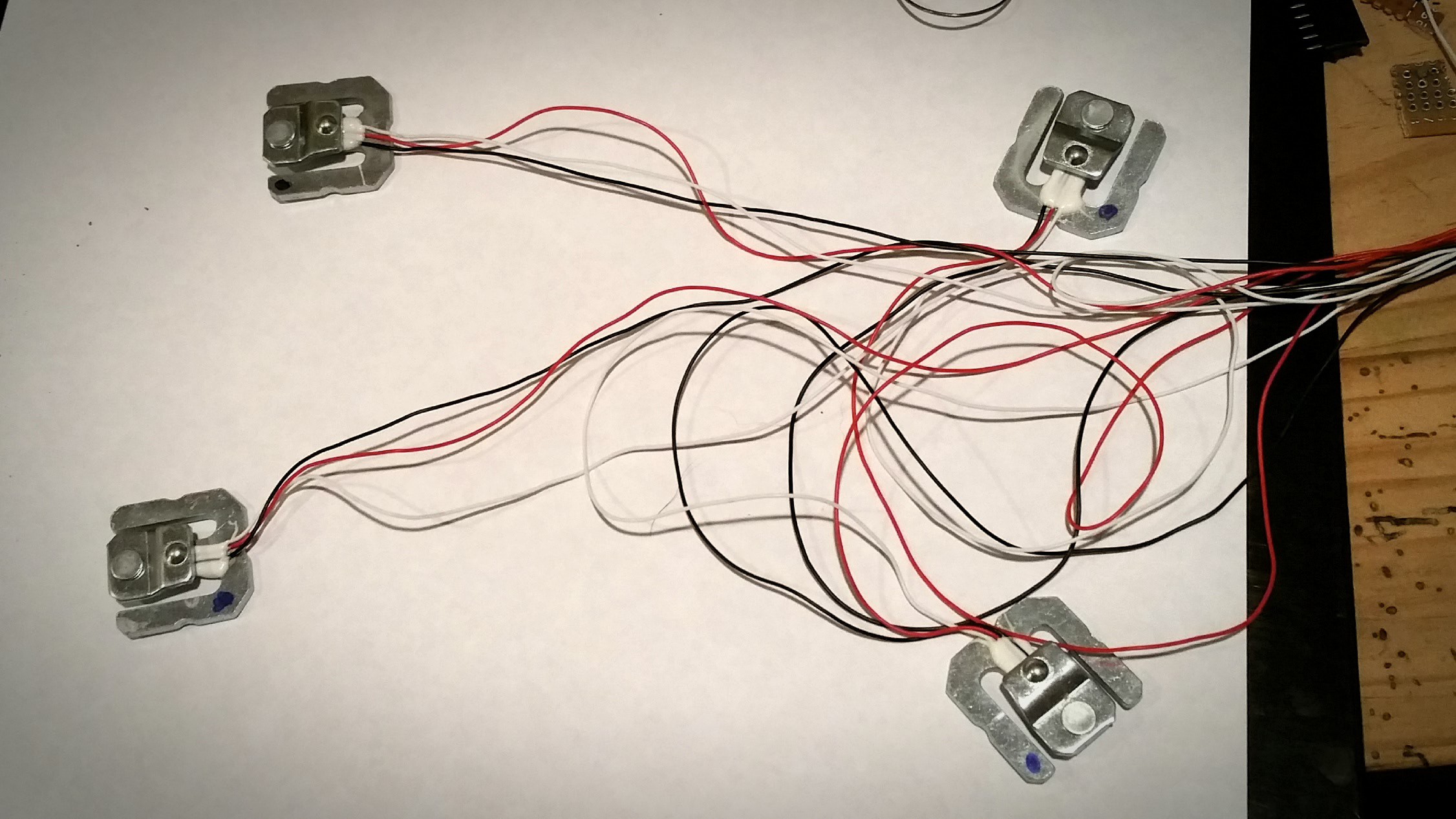
10/04/2015 at 01:41 • 0 commentsI was not happy with my current means of testing motors and getting reliable calibrated data from them, so I bit the bullet and obtained four 50 Kg load cells which will allow me to measure up to 200 Kg (over 400lbs) of thrust.
![]()
I went ahead and wrote up some software for the microcontroller to do some pretty nice analysis of the motor right after the test. The load cells are polled between 90Hz and 110Hz and implements a simple low latency regressive averaging scheme to get data. The results look very very promising.![]()
10 3.95
21 5.50
32 7.15
42 8.64
53 9.84
---------------
SNIP for Space
---------------
1590 1.99
1601 1.69
1611 1.58
1622 1.42
1633 1.32
1643 1.28
1654 1.10
Fire Complete

Burn Time: 1.67 seconds
Total Samples: 155 (92.54Hz)
Average Thrust: 30.74lbs (136.74N)
Total Impulse: 51.49lbs (229.04N)
Peak Thrust: 59.60lbs (265.11N)
Motor Designation: H136.7
You can see it gives the raw data with a millisecond timestamp, burn time, sampling data, average thrust, total impulse, peak thrust, and a moto designation. All nearly instantly after a test.
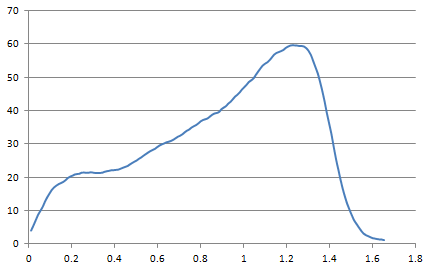
I can then copy and paste the raw data into Excel and get beautiful charts:
Thrust in pounds on the left, and time in seconds on the bottom. This graph is from a 'static test' of me pressing down hard on the sensors with a board on top.![]()
You can see how this will really help me scientifically narrow down engine performance and allow me to develop motors safely and efficiently.
I'll be constructing the new test stand shortly to allow use of these electronics on actual motors. Stay tuned!
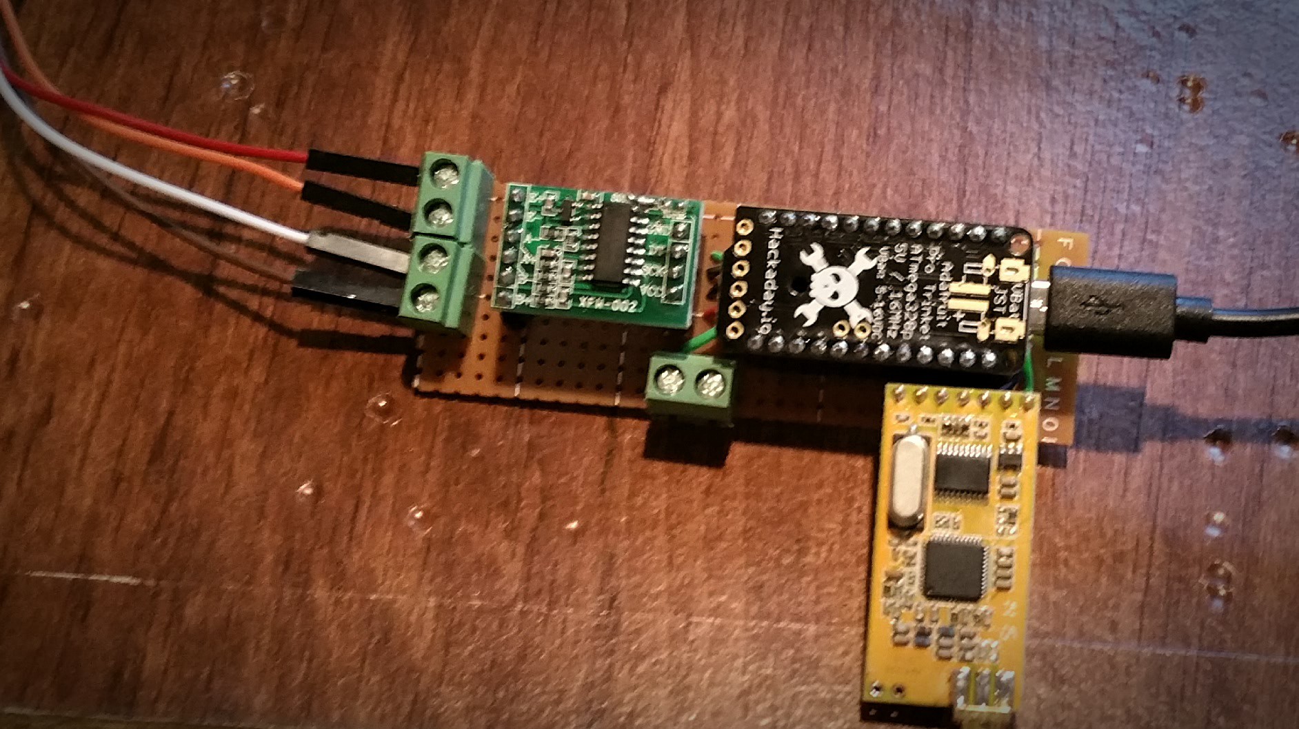
EDIT
![]()
Wired up the board for the electronics and added a wireless transceiver and connections for external battery connections.
Also, started a project page for this: https://hackaday.io/project/7942-rocket-motor-analysis
-
Motor and Nozzle Design
10/03/2015 at 01:03 • 0 commentsIntroduction
I've been working with a fellow rocketeer in his understanding and development of 1" PVC motors and thought this would be a good time to share the process on this project page. There will be a fair amount of math, but nothing overly complicated.
Please note that this design process is for the 65/18/17 mixture of potassium nitrate, light corn syrup/sucrose that is used in my motors, known as flexfuel due to its more flexible nature that is less prone to the brittle fracturing found in pure sucrose motors.
If this design is used with a 65/35 plain sucrose motor a CATO will likely occur due to over pressurization.
1" PVC had been shown to be structurally sound up to 1000PSI for burns up to and past 3 seconds. We'll be using a lower pressure for safety.
Equations
Some simple equations are necessary to understand this post, they are simple geometry equations related to circles and rectangles.
K = Effective ratio of of specific heats of the exhaust products, obtained from combustion analysis
Walk Through of Motor Design
I'm going to work out the design of a 1" PVC motor with a .375" nozzle. These values are picked for a couple of reasons, the diameter of the case allows for higher pressure, isn't too large (good for testing), and is readily available. The bore size is half the diameter of the case, 1/2". This allows for a decently high thrust at ignition and a decent (75%) case loading. The nozzle is smaller than the bore size to limit erosive burning.
One of the main concerns when developing a motor is the risk of over pressurization. KN allows for us to scale motors of different sizes by designing them by the burn area and nozzle choke size. This directly correlates to maximum pressure the case will endure during firing.
A KN of 350 has empirically been shown stable with 1" PVC. We will be using a single inhibited progressive burn fuel grain. This is one continuous grain that is case bonded on the outside, and both ends are inhibited with a single cylindrical bore through the middle. This allows for ease of casting, resilience under stress, and has the feature of easier mathematical calculation.
Now that we know we have a 1" inner diameter PVC pipe that can handle a KN of 350, and a nozzle of .375", we need to know how long the fuel grain needs to be. The first thing we need is the area of the nozzle choke area.
Since KN = Burning Area / Nozzle Area we solve for Burning Area:
We put in our values:
So now we know that the maximum burn area needs to be 38.6563 in^2. The highest amount of fuel burning will occur just as the fuel burns out. This is essentially the surface area of the outside of the fuel grain, which is the circumference of the inner diameter of the 1" PVC multiplied be the casing length.
We know that the BA is 38.6563 in^2, and that our diameter is 1". We solve for L (d is removed because in our design equals 1):
Our case is now 12.3" long and has a bore of 0.5" with a KN of 350 in relation to our .375" nozzle choke diameter.
The next thing we need to calculate is the nozzle geometry itself. It's been shown that divergent nozzle half cone angle is most efficient at about 11 degrees, however angles up to 15 degrees are very effective and save on weight. So we will declare 15 degrees as our divergent half cone angle, but to determine how far the nozzle geometry should extrude past the choke we need to calculate the optimal expansion ratio. The convergent angle has shown to be almost negligible in effects, but a 45 degree angle will limit erosion near the steel washer insert.
This next equation is a bit overwhelming at first glance, but just bare with me here. It's from Richard Nakka and calculates the optimal nozzle expansion ratio.
![]()
We are defining k as 1.16 from combustion testing, and a as 41 ATM (which is 600 PSI) for the internal chamber pressure. The pressure is derived from testing with KN values near 350, and gives a good starting point for calculation.
The result of this equation is: 6.52085. This is the expansion ratio that is optimum for our chamber pressure and fuel in relation to the area of the nozzle choke. Click here for the WolframAlpha Link to easily calculate this value.
So now we take our nozzle choke area, which is .1102 in^2 and multiply it by our expansion ratio:
This is the exit area from the nozzle that will match the ambient pressure to the pressure generated by our motor. To find the radius we do some more math.
Since this is still the radius, we double it to get our diameter.
This is a convenient number because .966 inches is very very close to our 1" inner diameter of our PVC casing.
Motor Design Finished Values
- 350 KN ratio
- 1" PVC casing
- 12.3" casing length
- .375" nozzle
- 15 degree half cone divergent angle
- 45 degree half cone convergent angle
- 6.648 expansion ratio
- .966 inch exit diameter
The initial KN value for this motor is right at 175. For faster chamber pressurization a sacrificial erosive nozzle can be cast in the choke. 3M fireblock caulking can be used to plug the nozzle choke, and a smaller nozzle drilled out. A 9/32" erosive nozzle will provide an initial KN of almost 310. As the burn progresses the nozzle will erode until reaching the concrete/steel washer. This method is not recommended for initial testing of this motor design due to over pressurization risks.
Conclusion
I hope that this helps some people in the understanding in the development of PVC motors that are safe and illuminates some of the math that is required in amateur rocketry.
Thanks to Steve Ghioto for some help with expansion math, Richard Nakka for a plethora of information on his website, and Dan Pollino for the flexfuel mixture.
High Power Experimental Rocket Platform
Experimental high power rocket with active stabilization, live telemetry, autonomous GPS guided recovery and HD video
 The obligatory storage case turned out quite well, with room for the drogue on top.
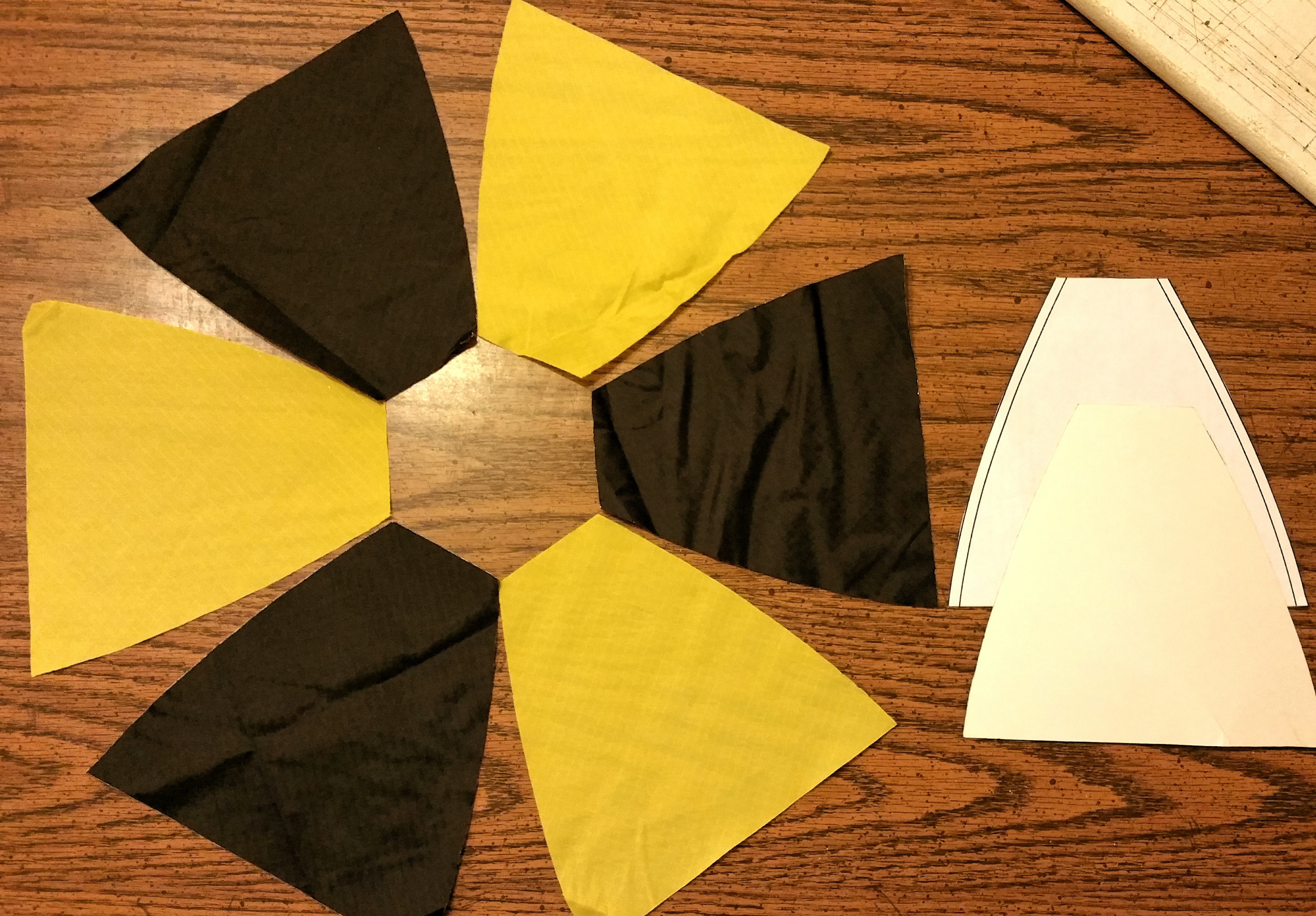 Each gore is cut out with a soldering iron on the bias (45° to the fabric grain) from 1.7oz ripstop nylon. Black and yellow was chosen for the color visibility reasons.