J. M. Hopkins
-
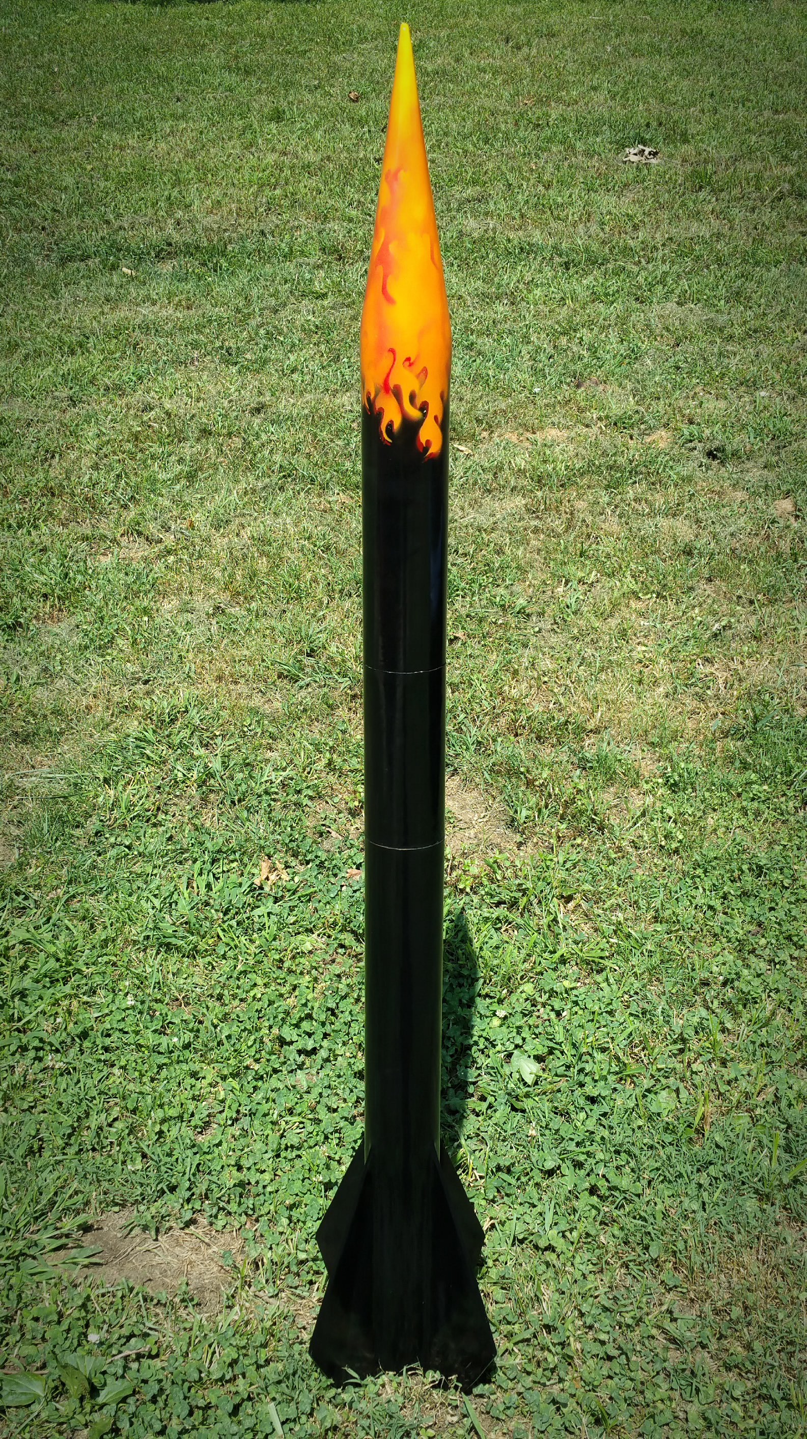
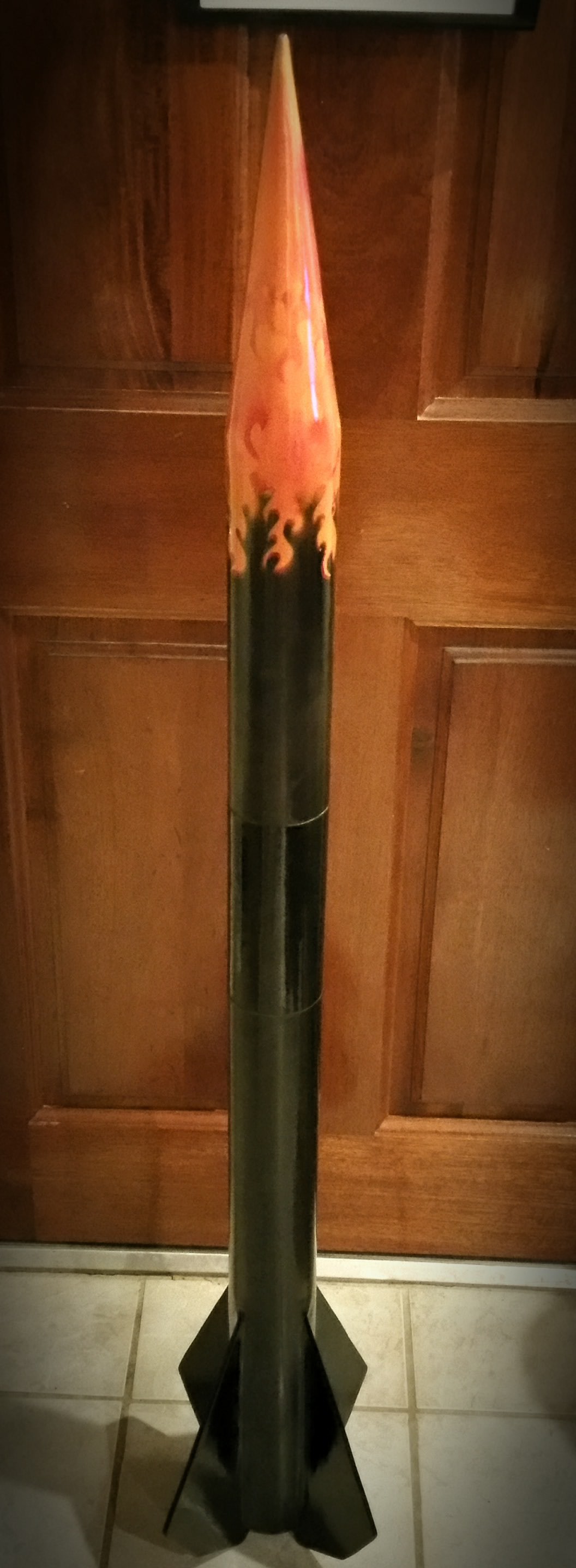
Paint Job, Natural Light
08/04/2015 at 20:16 • 0 comments![]()
3" Body tubing, standing 52" tall.
-
Electronics Board
08/03/2015 at 02:44 • 0 comments![]()
![]()
![]()
![]()
![]()
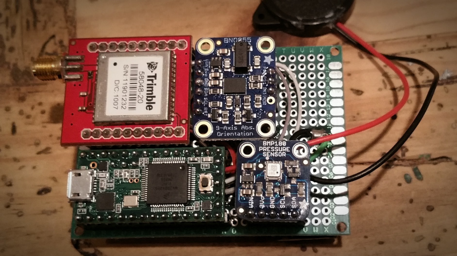
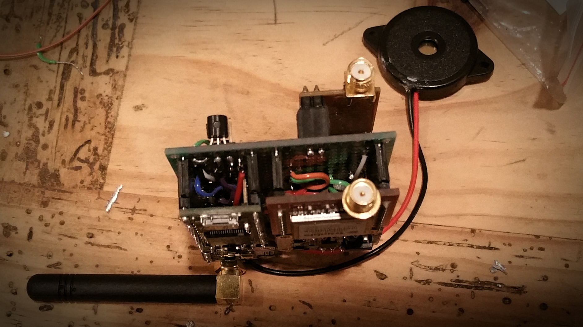
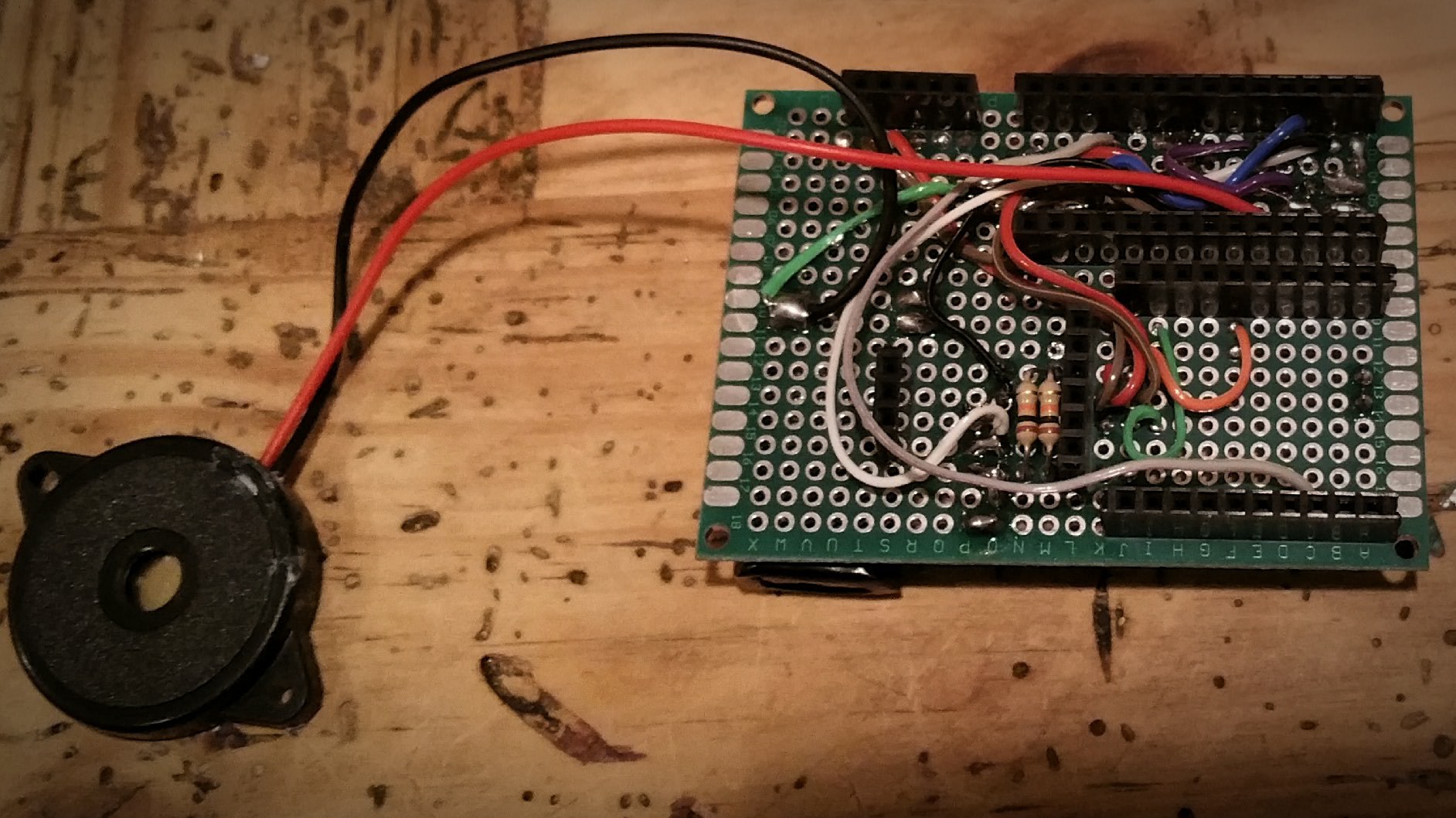
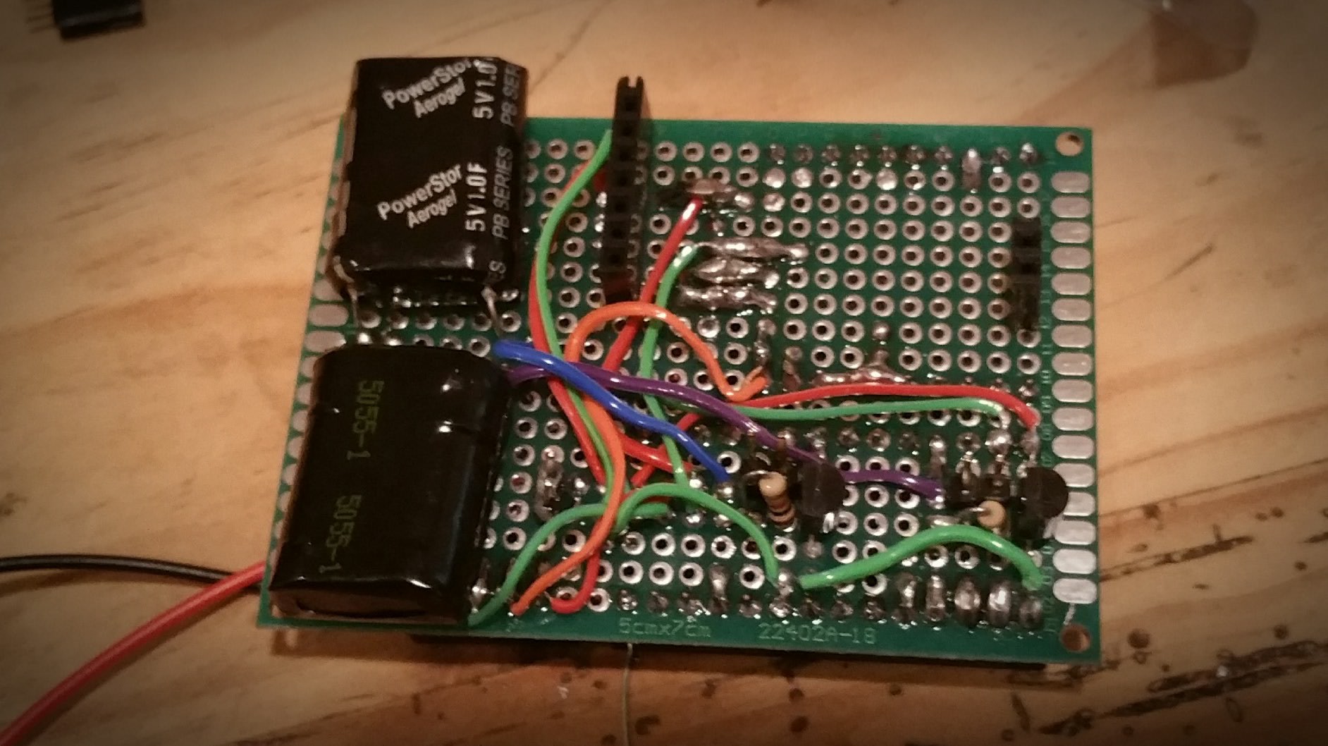
Lots of pictures this post... This is the flight controller board, containing all the wiring for the multitude of sensors and electronics.
Notice the super caps on the underside that allow for in flight ignition of ejection charges.
The serial connection has a simple menu interface that allows for remote arming and firing of the rocket and constant monitoring of telemetry in flight. Arming the rocket requires an arming code, and once entered, the buzzer warns everyone nearby that the launch is eminent.
-
Nose Cone Painted
08/02/2015 at 02:02 • 0 commentsFinally got around to painting the nose cone... Thanks to my wife for helping with the stencils!
![]()
-
Live GPS Tracking and Ejection Piston Testing
08/01/2015 at 21:23 • 0 comments![]()
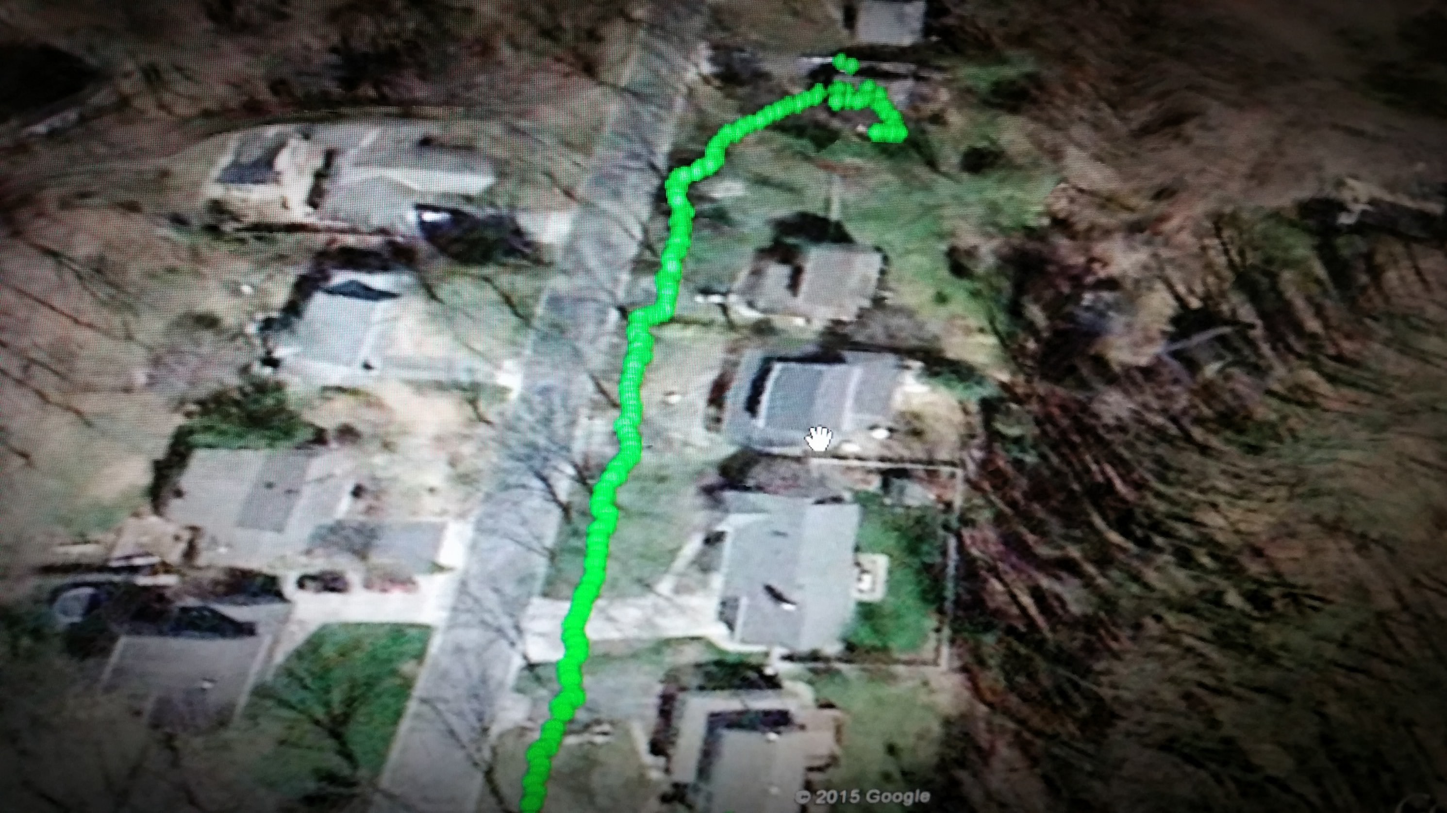
Live GPS Tracking into Google Earth is working. Took it down the block and back without issues with the Yagi setting upstairs in my office pointing out the window. The data stream also has all the other telemetry data stuck in.
I also did some testing of my piston ejection system. Working with 10g of dry mixed KnSu, provides quite a bit of pushing force.
-
Electronics Overview
07/30/2015 at 02:44 • 0 comments![]()
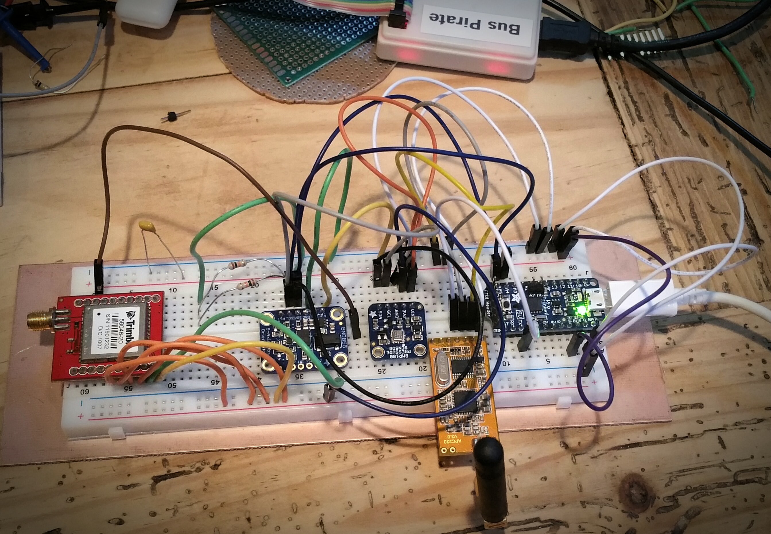
I've done a fair amount of work on the electronics side of the project. I've integrated the sensors, microcontroller, transceiver, and completed the remote ignition circuitry.
Onboard there is GPS, a full IMU (providing accelerometer, gyroscope, and magnetometer, heading and temperature data), and barometric sensor (with an additional temperature sensor).
The 70cm transceiver is running at 20mW, which seems really low, but with the yagi and LNA I can close the link at quite a respectable distance. More testing on that later. The datarate is 4800 to allow better Eb/No at the low power levels. An optional 1 watt power amplifier can be added if needed, but I'd rather avoid the battery penalty involved with that.
The igniters I have are electronic matches, and ignite off with 400mA of current, so a smaller battery or even small 5V 1F super capacitor will work as the current source. They use a signal from the microcontroller and an NPN transistor to send current from the ignition battery (or capacitor) to the igniter. Appropriate safety toggle switches will exist for RSO peace of mind. I'm thinking on the remote ignition side that launch commands can be given along with a safety "Launch Code".
Data is sent back in a data stream similar to NMEA, but adds additional details from the other sensors at a rate of about 5Hz. This data will allow the base station to track the rocket live in Google Earth and custom telemetry screens. A terminal console will enable remote commands.
Once circuitry connections are finalized I'll solder up the PCB and get ready for rocket integration.
-
435MHz Yagi Antenna for Telemetry
07/28/2015 at 03:13 • 0 comments![]()
![]()
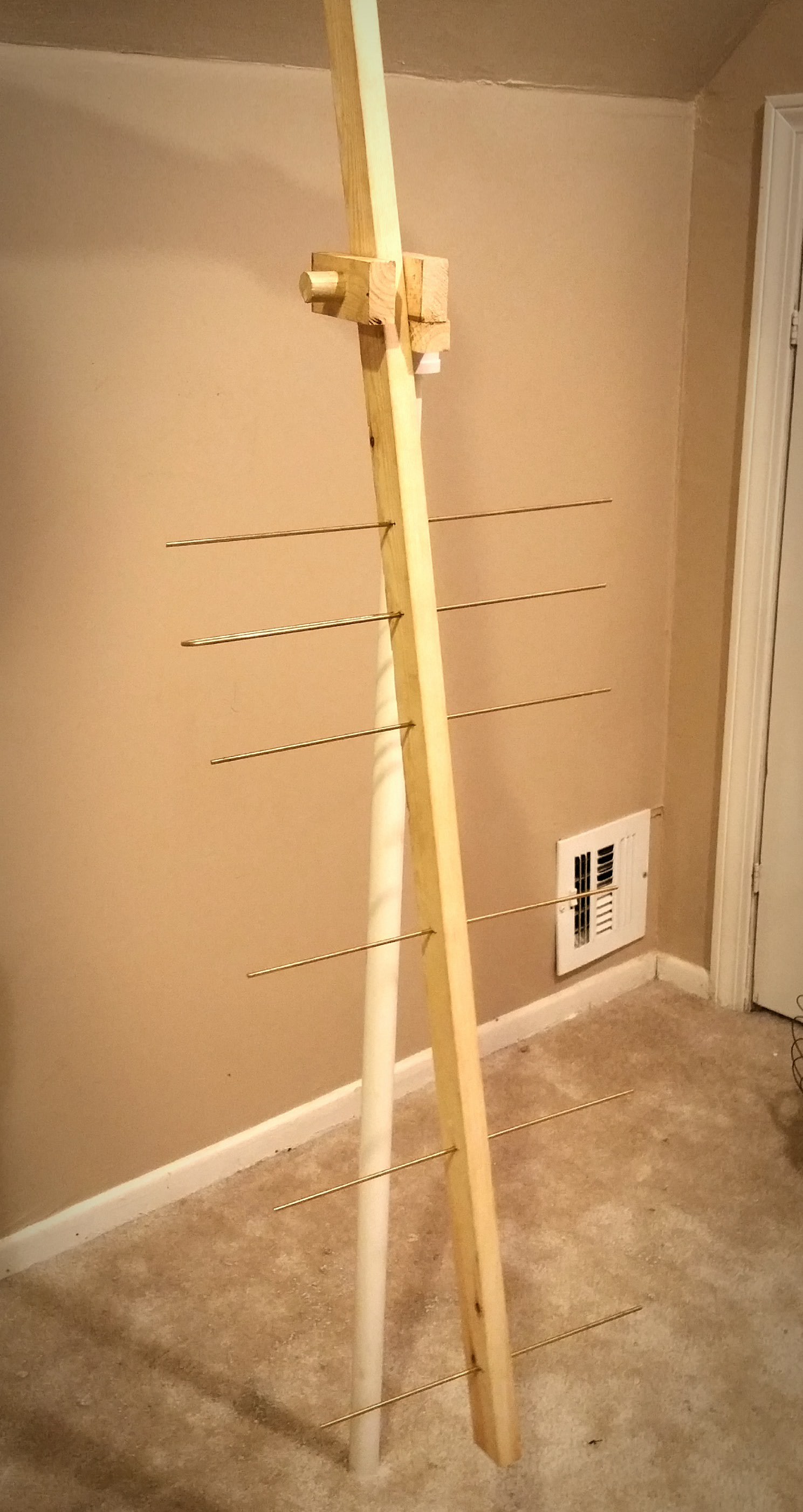
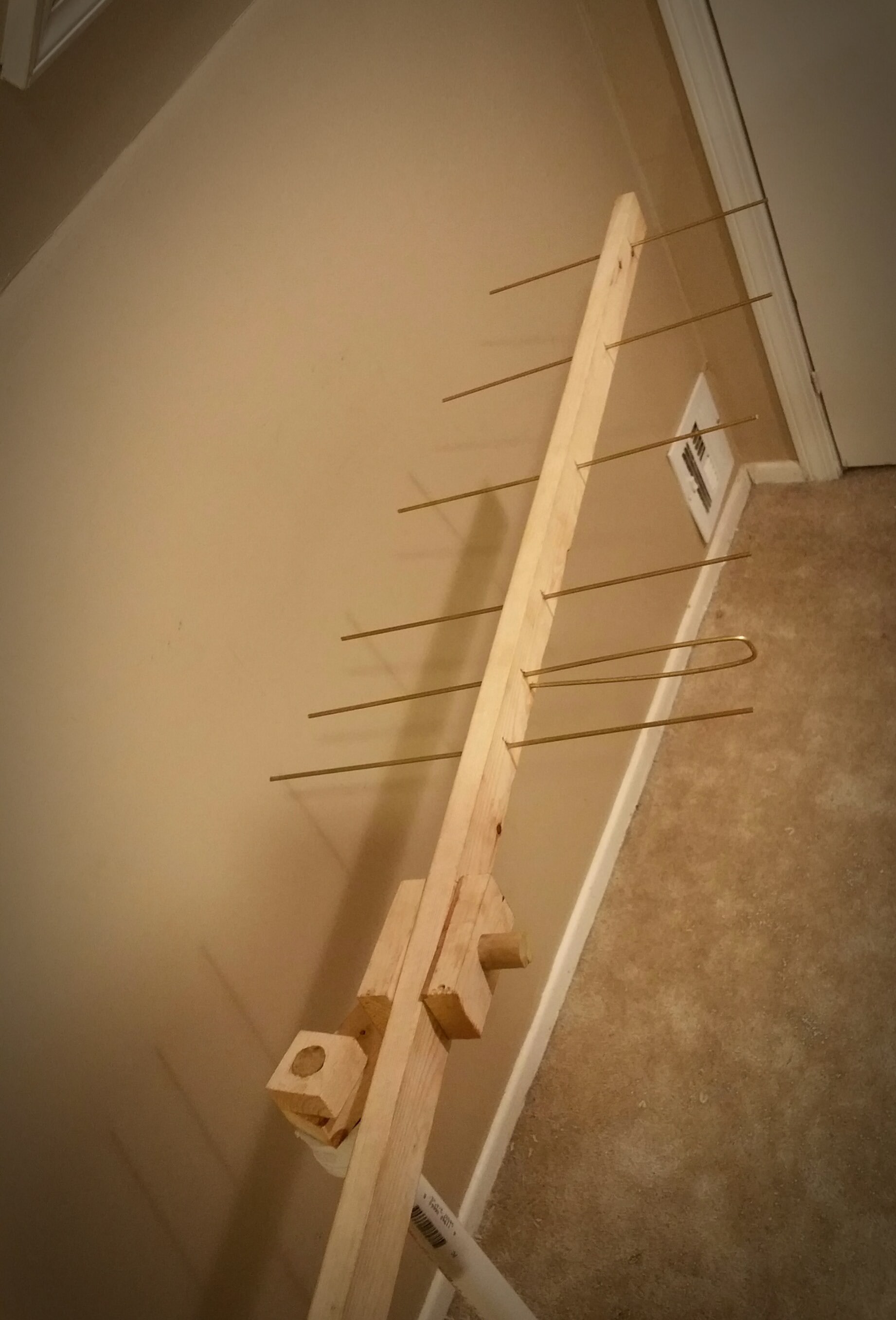
Completed a 435MHz directional Yagi Antenna for rocket telemetry. It can pivot in X and Y axis and should provide quite a bit gain over the omnidirectional antenna on my transceiver. As the rocket launches, a helper (my beautiful wife), will track the rocket with this contraption so that my computer can maintain telemetry lock. The computer will show a live view inside Google Earth and also a separate telemetry window and serial console for remote commands.
I still need to actualy wire in the cable and adjust the elements, but the hard part is done.
Pivoting is accomplished via two 3/4" dowels that are attached at different axis points.
I might take a flush cut saw to the Y axis dowel.
-
ST015 - 1D/16C/.5B/.375N/335P
07/26/2015 at 14:11 • 0 comments![]()
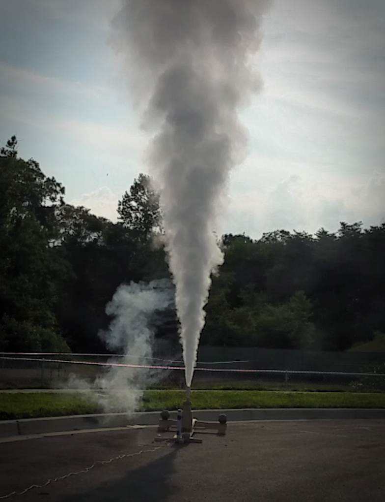
The image of this static is with a lot of morning backlight which drowns out the image a bit.
This was the second test on my new thrust measuring stand and I received some good data this time.
![]()
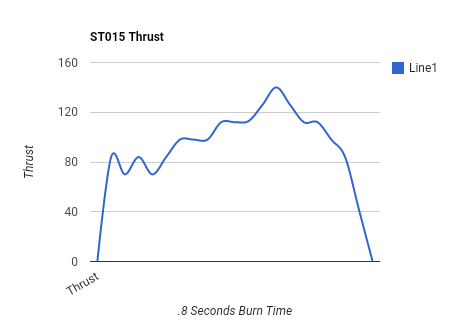
This data gives a 91% H motor, classified as H367. This seems a little low and might be due to stand calibration issues. I was expecting more of a lower to mid level I class. The graph shows thrust in pounds to clarify any confusion.
The progressive burn rate was expected, but the larger regressive side was a bit interesting as I was expecting more of a sudden drop off.
This thrust characteristic might also be due to longer ignition time causing the bore to burn more fuel at the top of the motor prior to full bore ignition. This would allow a tapered erosive burn profile to occur which would match the graph.
-
Rocket Body, Motor, and Parafoil
07/25/2015 at 18:14 • 0 comments![]()
This picture shows the size between rocket and motor. I was hoping for better finishing on the rocket itself, and I'm still thinking about adding the flame detail on the cone.
I'll be working on integrating the electronics and parachutes next.
![]()
-
ST014 - 1D/15.5C/.5B/.375N/335P
07/25/2015 at 03:23 • 0 commentsTested my 15.5 inch casing today on my new thrust measuring stand. The stand was set to max at 135lbs of thrust and the motor exceeded this for most of its .8 seconds burn time.This puts the motor into the mid I class.
I also prepared the 16" casing which I believe will be my final iteration of 1" motors providing a max Kn of 455.
![]()
Sorry for the image, but I didn't bother transferring the video after failure of maximum thrust measurement.
![]()
And here's an image showing the size difference between 11" low Kn and the 16" high Kn (455) motors.
-
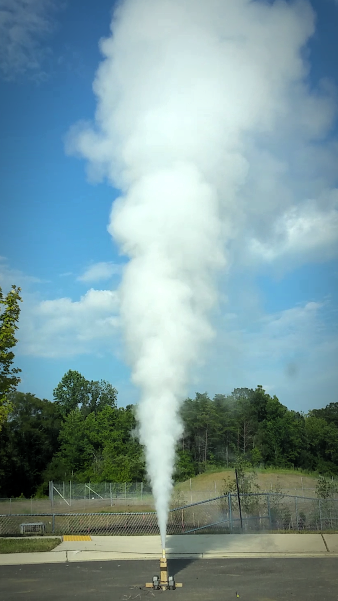
ST013 - 1D/14C/.5B/.375N/300P
07/22/2015 at 02:26 • 0 comments![]()
Successful testing of my 14" casing.
I apologize for the camera aspect ratio again, but it allows for more exhaust plume capture.
High Power Experimental Rocket Platform
Experimental high power rocket with active stabilization, live telemetry, autonomous GPS guided recovery and HD video