 cheese
After over a year and a half of silence from this project, I am finally going to complete it. While moving interstate I found all the components for this project in storage - surprisingly the LCD display and driver board still functions, I found it and all its delicate cables and screen tangled up in a huge box of junk tech - along with the goggles.
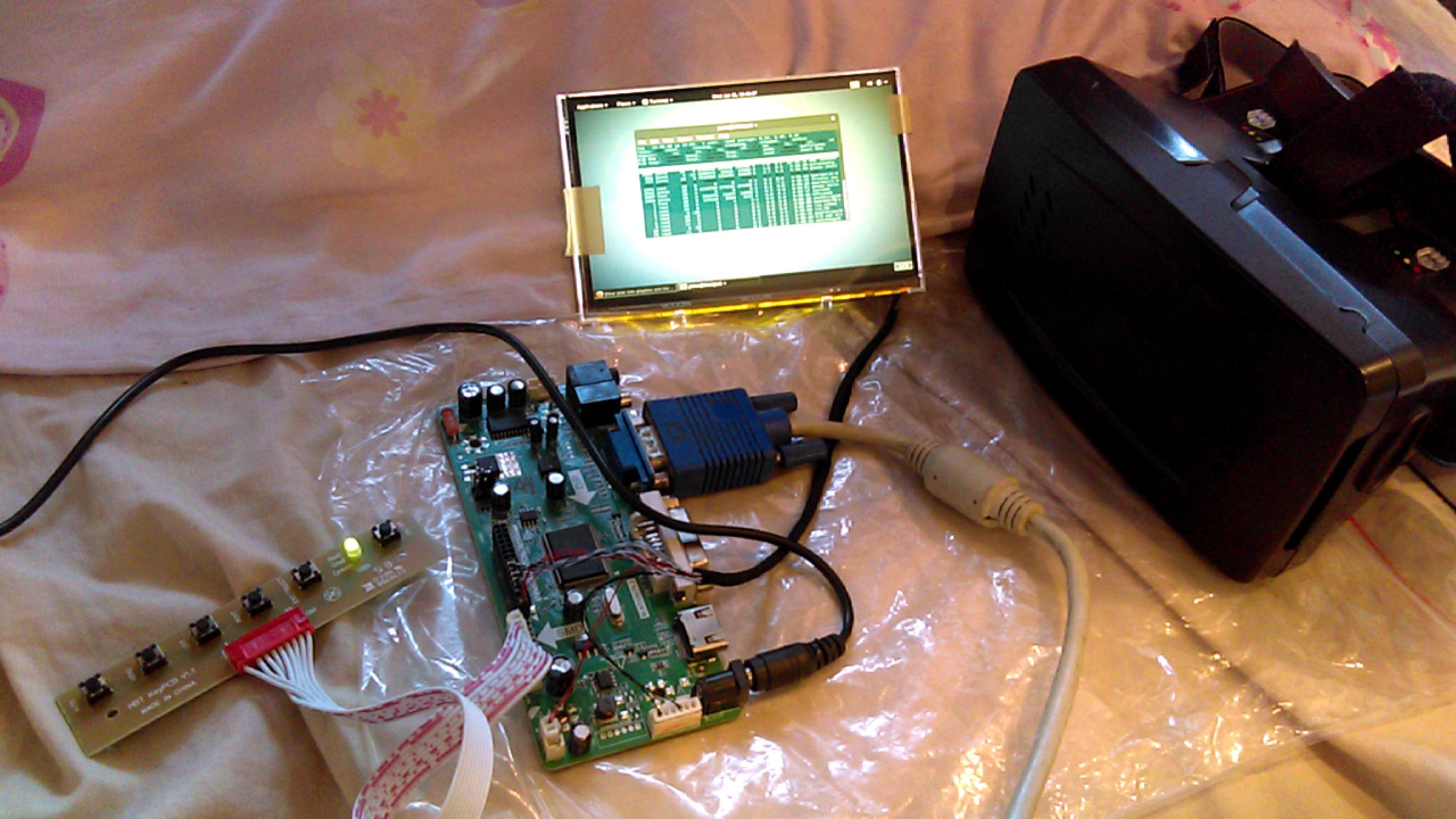 In the last post I made (all the way back in 2016) I failed hard at removing the IR filter from a PS3 eye - which was going to be used for head tracking. I have decided to use the DIY EDTrack head tracking solution in place of the IR LED array I originally "designed". I'm still waiting on the components in the mail, but from what I have researched into the solution so far, it is looking like it is the most efficient head tracking solution for its price.
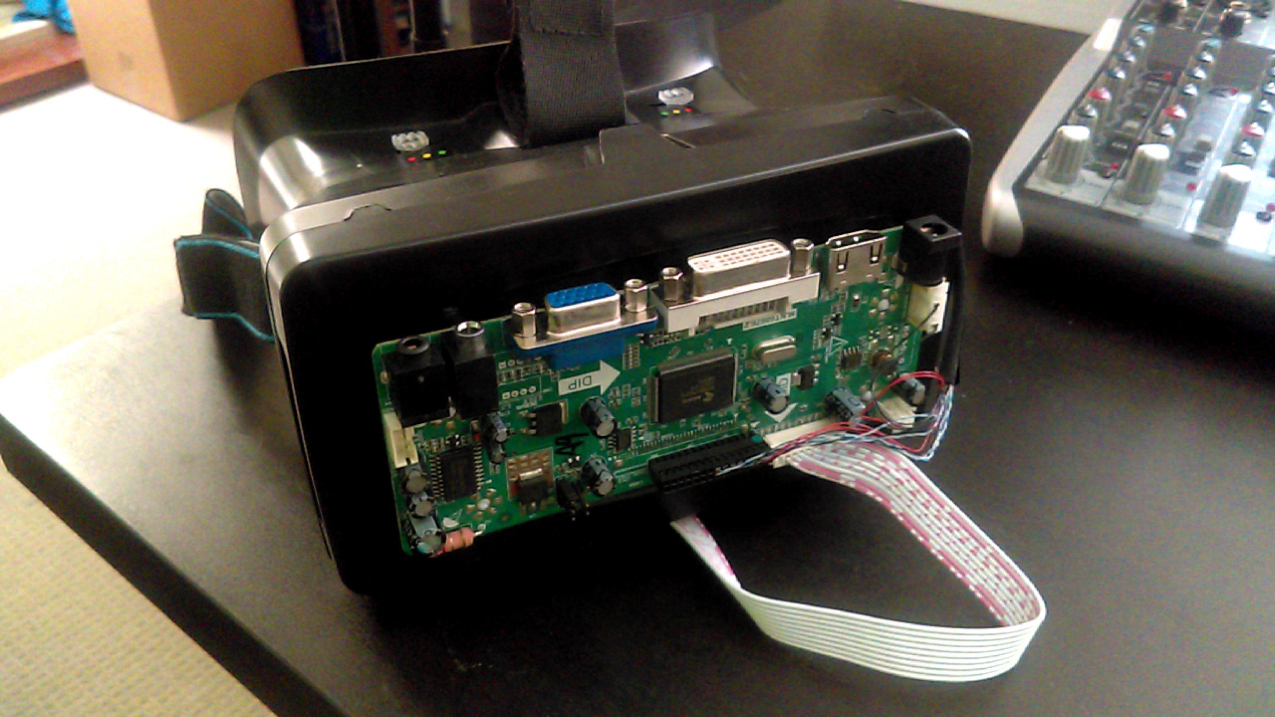
So to begin with I mocked the rough positioning of the boards on the goggles with blue tack. Given the positioning of the various ports on the panel driver board, I decided on placing the switch board underneath (image below). This is to ensure that there is no obstruction for cables that need to be plugged into the board (power and HDMI), as well as providing space for both the head tracking chip and it's connected USB cable.
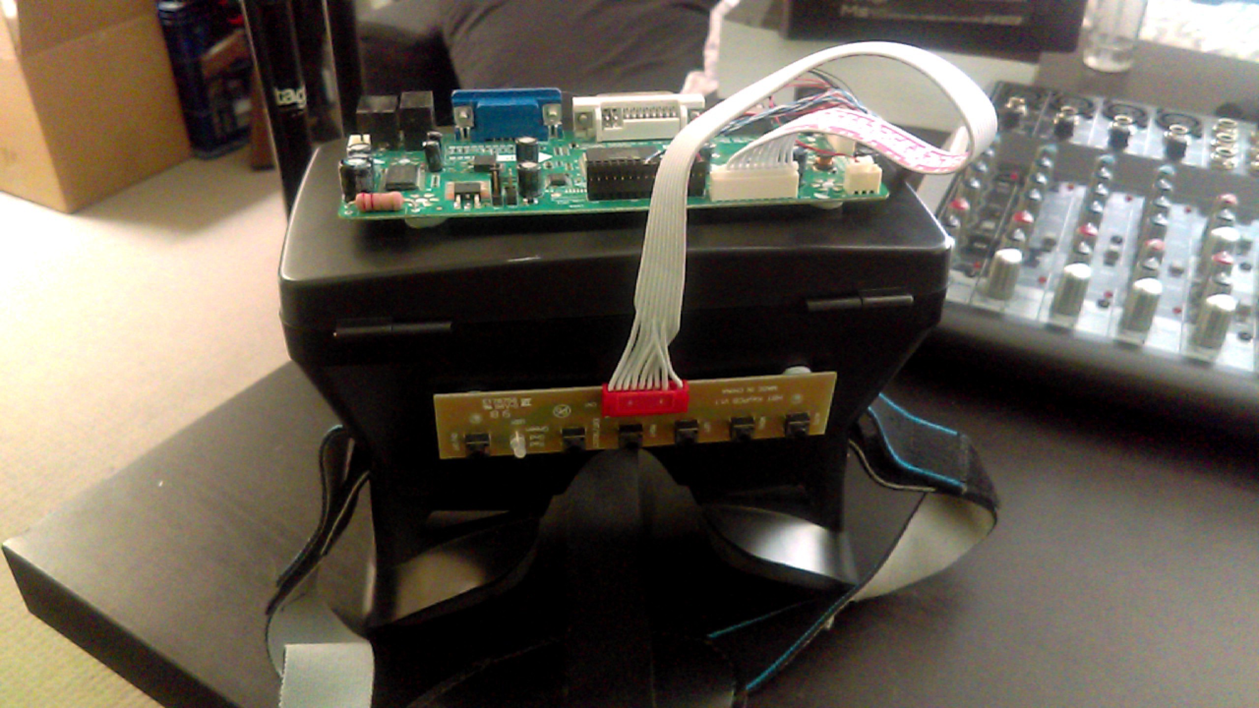
This process was purely so I could visualize the layout of the device, the placement of the various components and the finished product. I have decided on keeping the PCB's visible in place of creating housing for both boards - it looks dirty tech and cool af. Next up is attaching the two boards to standoffs and gluing the standoffs in place on the goggles.
Discussions
Become a Hackaday.io Member
Create an account to leave a comment. Already have an account? Log In.