 Jithin
Filter study
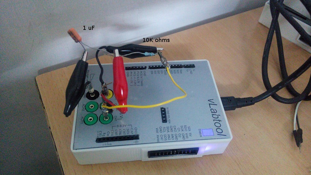
A simple low-pass RC filter was made with a 10K resistor and 1uF capacitor. The input was taken from the programmable sine wave generator, and simultaneously monitored via CH1 . The output(midpoint of R and C) was also monitored via CH2.
Frequency was swept from 10Hz to 500Hz, and the amplitude and phase plots are shown
Photograph of the setup:
Diode IV characteristics
A 4148 diode's IV characteristics are plotted.
Input is taken from a 0-3.3V DAC (PVS3) , and fed to a 4148 diode via a 1K resistor. The other end of the diode is grounded via a current to voltage convertor.
IV plots are obtained by plotting the voltage across the diode versus the current
Discussions
Become a Hackaday.io Member
Create an account to leave a comment. Already have an account? Log In.