 Jithin
A waveform generator is a must for studying a variety of electronic phenomena such as resonant frequencies, filter characteristics, etc. , and the vLabtool includes a 28-bit DDS( 0.03 Hz resolution at 16MHz clock.) with manual amplitude control from +/-20mV to +/-4V.
The DDS(Direct Digital Synthesis) Approach to waveform generation involves a pre-programmed lookup table containing the amplitudes of the waveform to be generated. The processor then loops continuously through this table, and feeds each amplitude to a DAC, resulting in an analog waveform being generated at the output.
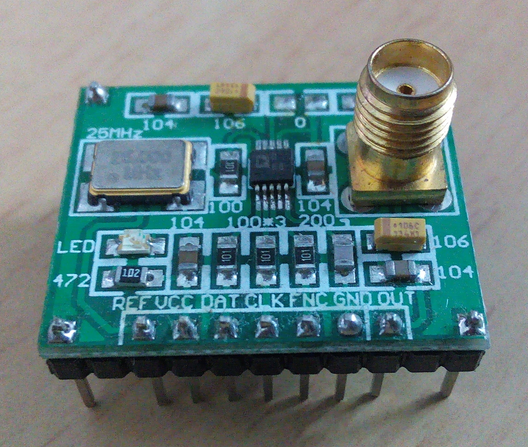
Initially, I ordered a couple these breakout boards for the AD9833 DDS. Once the communication protocols and usability were confirmed, it was added to the base board. The output of this breakout is 0.6v p2p (DC blocked with a capacitor).
Additional circuitry required to make a usable output.
- The amplitude of the AD9833 is fixed at 0V - 0.6V for the sine and triangular waves. This felt rather restrictive . Adding a level shifter, and manual gain control results in a bipolar output which can be adjusted from +/-10mV to +/-4V.
Frequency control
- Two 28-bit frequency registers are present on this IC. This is aimed at applications like Frequency Shift Keying. Once both frequencies have been loaded, one can quickly toggle between the two. The maximum clock frequency is 25MHz , and this allows generating waveforms from 0MHz up to 12.5MHz(If you're okay with 2 points per waveform). On the vLabtool, the DDS is driven with a 16MHz clock generated by the PIC24E . 16MHz,28-bit equals 0.03Hz resolution. Neat looking frequencies can be seen up to 2MHz. Beyond this, the scarcity of points will force using another analog filter.
- A 12-bit phase register is also present, and this can be used to set a fixed phase difference between two AD9833 ICs running off the same clock, and outputting the same frequency( or a harmonic ). The phase registers have been used on the Python Powered Scientific Instrumentation Tool since it has two AD9833s on the base board itself. Phase control won't be useful on the vLabtool unless an Add-on board with another AD9833 is used. Keeping this in mind, the 16MHz clock of the AD9833 is also routed to the 20-pin expansion slot.

This is the portion of the schematic that deals with the AD9833. The gain control slider is a 50K dial potentiometer.
Choosing an appropriate DC blocking capacitor is essential for achieving constant amplitude throughout the frequency range. I actually experienced this when I accidentally used 0.1uF instead of the 10uF. Since the vLabtool also has an oscilloscope, it was used to record the output for frequencies spanning the intended range. The output curves were fitted using Scipy, and the extracted amplitudes were plotted against the corresponding frequency.

Figure: ERRONEOUS frequency response curve of the DDS resulting from a misplaced capacitor! . Ignore the blue trace, it's not relevant here.
Replacing the 0.1u with the right value(10uF) gave an extremely flat amplitude response at 4V starting from 5Hz.
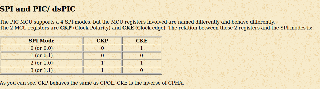
The SPI input of the AD9833 is very picky when it comes to modes. Both CKE, and CKP must be set to 1. Accidentally pushing values with wrong mode settings causes the IC to not respond until a hard reset. All this has been taken care of in the firmware. In case you're not familiar with CKE, CKP terminology, here's a map (taken from here).
Discussions
Become a Hackaday.io Member
Create an account to leave a comment. Already have an account? Log In.