 Antti Lukats
Easiest way is to use the ICEd board as DIPSY Programmer, then it would be recognized by Lattice Programming tools directly on USB Port 1 (FTDI Channel B).
Step by Step:
0: Assume ICEd board is preflashed with "DIPSY Programmer" FPGA code (it is available in github ..\THP2015..)
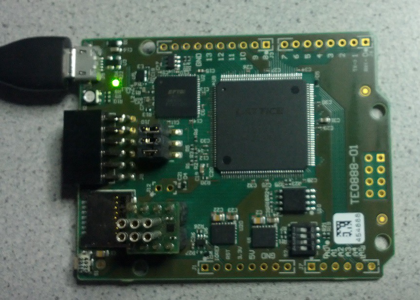
1: Insert DIPSY into the socket
2: Connect micro USB Cable to ICEd
3: Start Lattice Diamond Programmer 3.5
4: Click "Detect Cable"

This shows that FTDI on ICEd is detected and selected as USB Programmer (not in the screenshot, some scan result is displayed from old programmer project, with fresh new one there would be empty screen),
5: Select FTUSB-1 as "Port" this would direct programming operations to DIPSY and not the HX1K on the ICEd
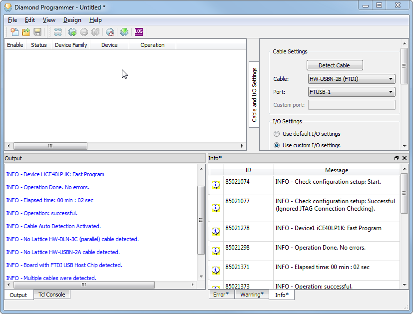
FTDI Channel B (FTUSB-1) selected as USB port
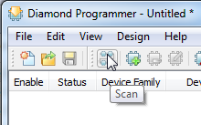
6: Click on "scan"
7: You should see this
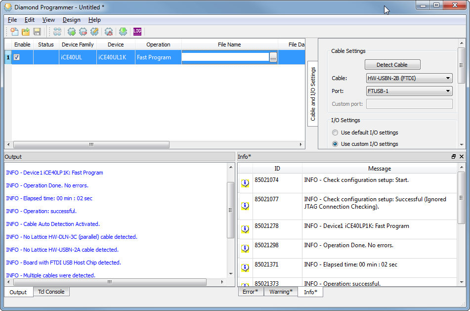
8: Click on "..." to select Programming file, can for test choose file from the DIPSY gihub repo .. /THP2015
https://github.com/AnttiLukats/DIPSY/tree/master/THP2015/AVR_SoC
there is "blink.bin"
9: Click on the green arrow to start programming
10: RGB LED should blink on DIPSY (not on ICEd)
Congratulations:
You have configured DIPSY with AVR RISC Based custom System on Chip "binary code" that did configure the LUTS and FLIP FLOPs to "emulate" the AVR processor HARDWARE, and this processor is now running AVR Object code.
Discussions
Become a Hackaday.io Member
Create an account to leave a comment. Already have an account? Log In.