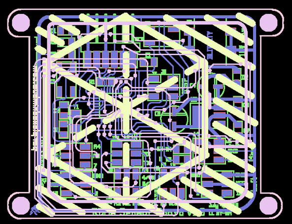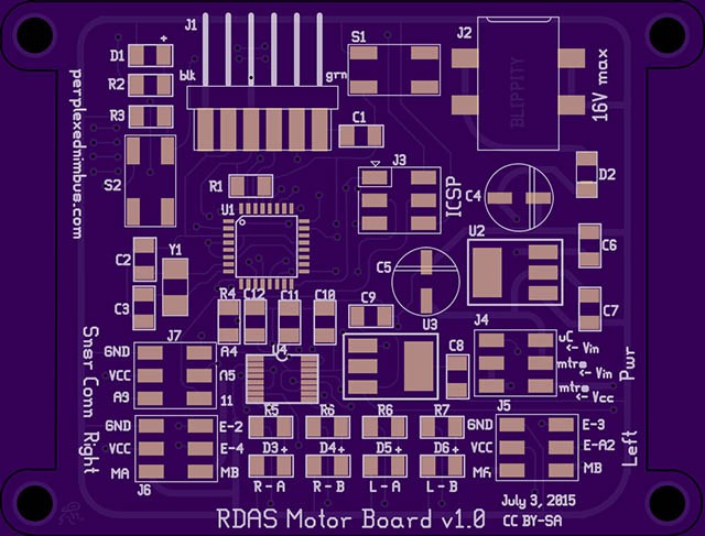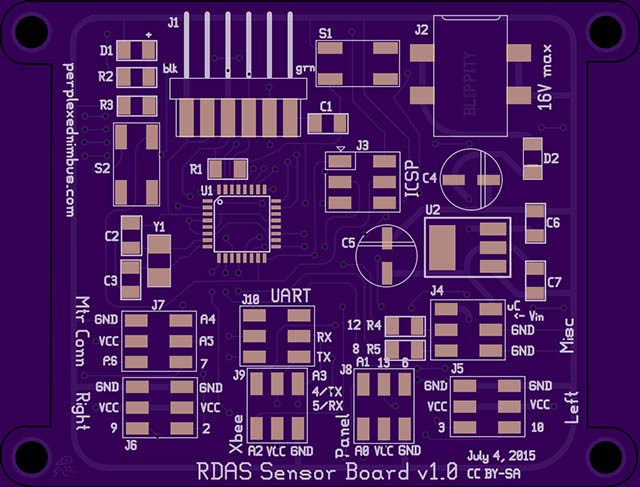
Designed pcbs- the motor board and sensor board.
Specs:
Dimensions: 7.84 cm x 5.96 cm
Layers: 2
Trace width: 7mil
Larger trace width: 30mil
Clearance: 10mil
Via drill width: 15mil
Via copper width: 35mil
Via annulus: 10mil
Mounting hole diameter: 4mm
Read on to see screenshots of the sample boards
Motor board


source:
https://github.com/RobotGrrl/fabacademy/tree/master/motor_board_v1.0
Sensor board


source:
https://github.com/RobotGrrl/fabacademy/tree/master/sensor_board_v1.0
BOM, pinouts, available here:
http://fabacademy.org/archives/2015/na/students/kennedy.erin/project_electronics.html
 EK
EK
Discussions
Become a Hackaday.io Member
Create an account to leave a comment. Already have an account? Log In.