After many months I finally have the first order of ESP8266 based Tick Tock Timers.
There was actually 2 revisions of the ESP8266 version due to a few pin behavior issues.
All GPIOs on the ESP8266 are being used by the Tick Tock Timer so choosing the function of each pin became a problem when some anomalies were discovered with certain pins.
Issue 1: Relay Closing/Opening at boot.
GPIO 0 was being used to trigger the relay as this was supposed to be a very basic function, however when the ESP8266 first boots this pin goes low for a moment, causing the relay to sometimes close/open when powering on. This had to be switched to a more boot stable pin. Pin 0 become LCD CS it is not effected by this boot low behavior and the relay became pin 10.
Issues 2: LCD Backlight pulsing when dimmed
GPIO 15 was being used to generate PWM to control screen brightness however when the PWM value is set < 400 the I noticed the screen brightness would pulse every second. An oscilloscope confirmed that the pin was unsuitable for stable PWM generation. Backlight was moved to 16 at it proved stable for PWM and Touch CS
was moved to 15.
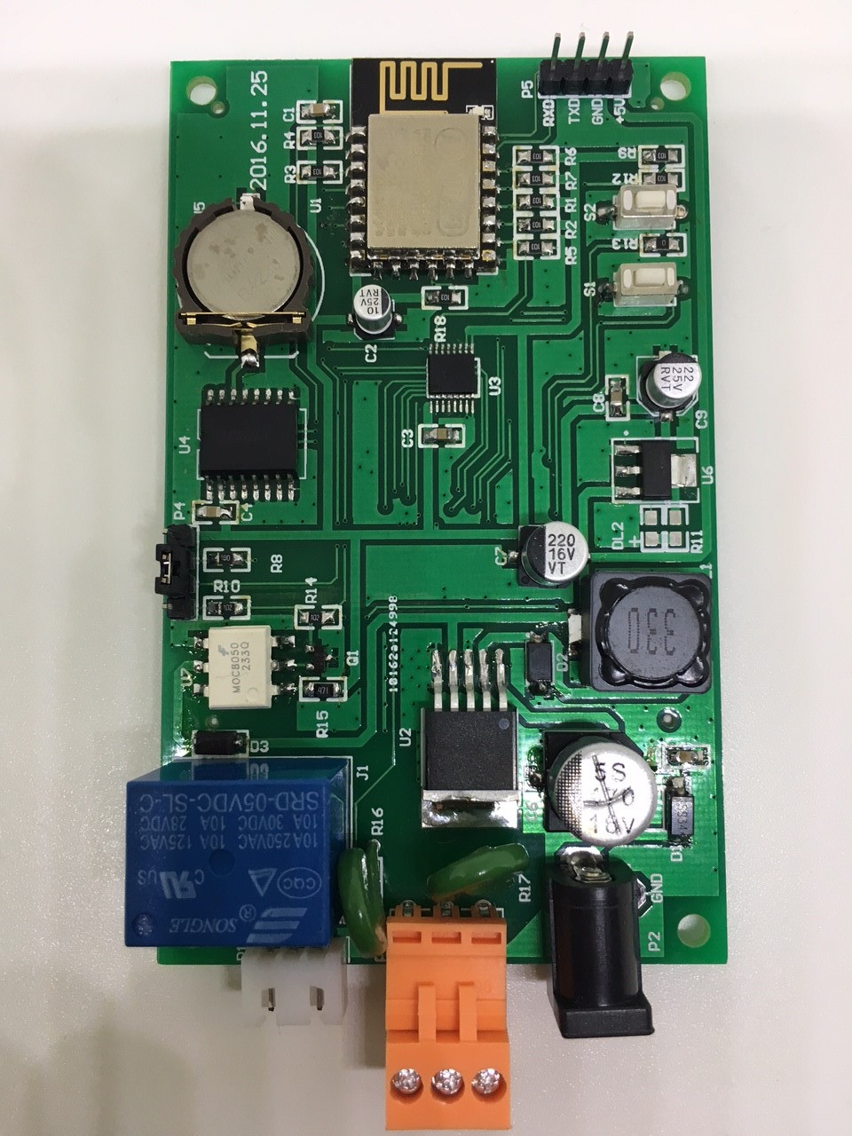
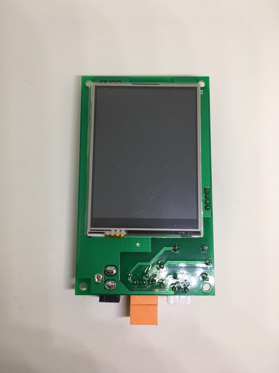
Here are some pictures of the new hardware.
Summery of changes
- ESP8266 (Originally MEGA2560)
- SPI ili9341 (Originally ili9325 8Bit)
- Operating Voltage 6-24v (Originally 6-9v)
- Opto-coupled relay protection added
Discussions
Become a Hackaday.io Member
Create an account to leave a comment. Already have an account? Log In.