Setup
The powersupply came from an old Nokia Charger. I extracted the litte pcb out of the plug housing and mounted it isolated together with this stripboard pcb in the machine. The original button was disconnected from the ac mains and connected to a digital port. Instead the relay was connected between ac mains and the grinder motor. Two holes were drilled in the frontpanel for mounting the switch and poti.
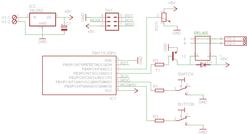
Eagle Schematic
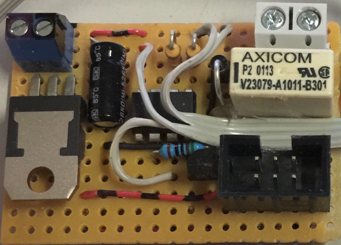
PerfBoard
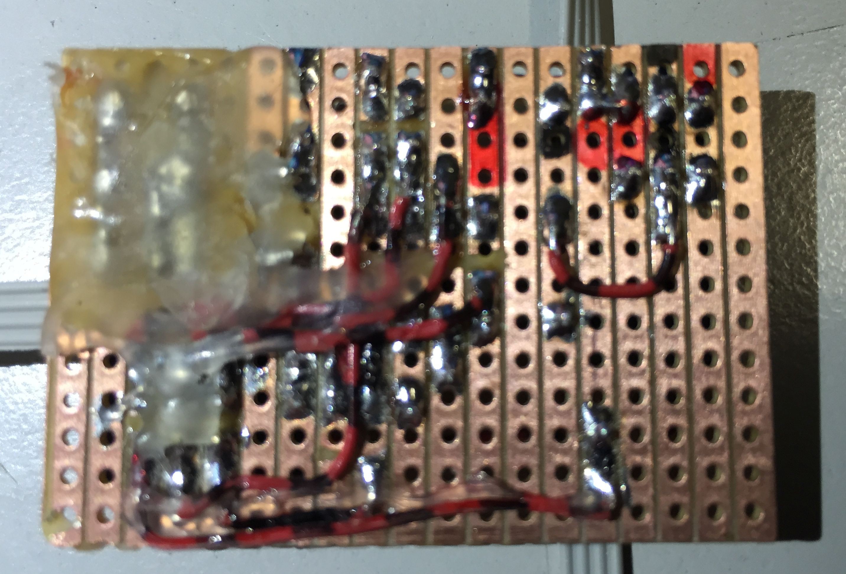
StripBoard bottom
Arduino Code
#define POTI A2
#define SWITCH 0
#define BUTTON 1
#define RELAIS 3

int value=0;
int state=0;
unsigned long starttime=0;
unsigned long duration=0;

void setup() {
  pinMode (POTI, INPUT);
  pinMode (SWITCH, INPUT);
  pinMode (BUTTON, INPUT);
  pinMode (RELAIS, OUTPUT);
  digitalWrite (SWITCH, HIGH);
  digitalWrite (BUTTON, HIGH);
  digitalWrite (RELAIS, LOW);
}

void loop() {
  if (digitalRead(SWITCH)==LOW){
    //Timer Mode
    value = analogRead(POTI);
    duration = value * 10;
    if (digitalRead(BUTTON)==LOW){
        if (state==0){
            starttime=millis();
            digitalWrite(RELAIS, HIGH);
            state=1;
        }
        else{
            if (millis() - starttime >= duration){
                digitalWrite(RELAIS, LOW);
                delay(250);
            }
        }
    }
    else{
        if (millis() - starttime >= duration){
            digitalWrite(RELAIS, LOW);
            state=0;
        }
    }
  }
  else{
   //Momentary Mode
   if (digitalRead(BUTTON)==LOW)
       digitalWrite(RELAIS, HIGH);
   else{
       digitalWrite(RELAIS, LOW);
       state=0;
   }
  }
}
 Charles Dean Modrich
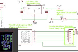

 Daniel Frausto
 ElectronicABC