Ossum
Ossum-
Wrap Up Video
02/09/2016 at 08:21 • 0 commentsAfter getting a new motor and prop (10x7 now), I finally got the boat up to planing speed. It is still a long way off fast, but I think it is successful enough that I can put the project to rest.
If I had the dough for a decent ESC/Motor combo that could handle 4S then I am sure it would be quite a bit more exciting, nevertheless, here is some video for all y'all as it stands.
-
It Floated!
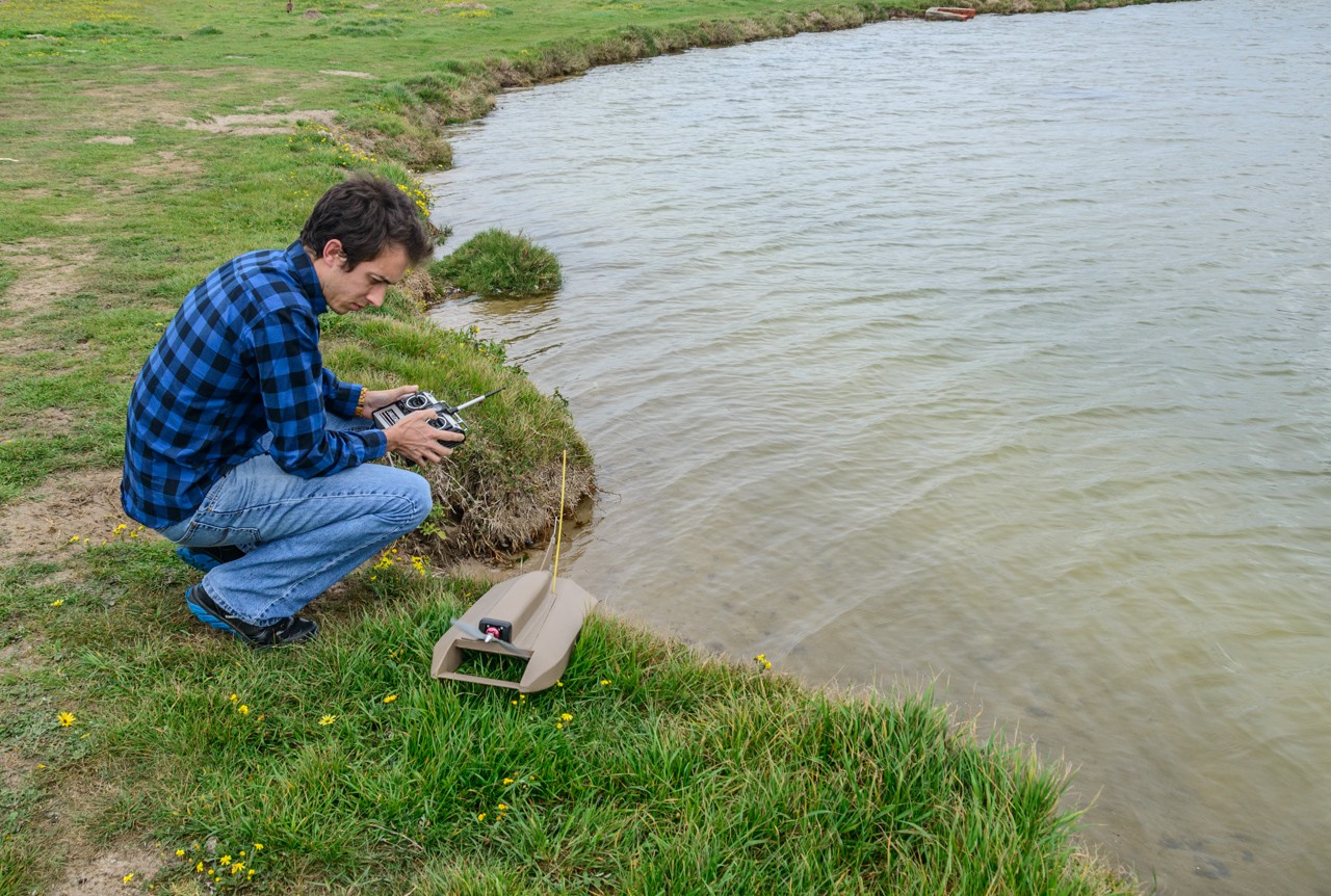
09/21/2015 at 20:13 • 0 commentsIt feels like it has been ages since I started this project, but three months after find the plans it finally hit the water. My dad was good enough to come along and take some photos. The wind was blowing a bit, so we headed for the most sheltered section of the lake.
First a final functional check to test that the was moving and the motor was responding. Apparently I am not NASA material, because I didn't notice that the rudder was moving backwards, fortunately I was able to flick the reverse switch in the back of the remote easily enough.
![]()
You can probably see the problems in this photo already, but at least it's floating!
![]()
The boat sits a little low, but that shouldn't be a problem when it gets up to planing speed. Unfortunately, it just can't get there. There were a handful of reasons:
- The prop is pretty small (I am going to look for a 3-bladed 7x5, or something even more aggressive than the current 7x5
- The prop is nicking the water, so I don't think it is getting up to full RPM. I am going to try and raise the motor.
- The motor could be more powerful I guess, but I have no idea what this one's ratings are, and I don't have any others to try.
- I could run this motor on 3S (it is currently on 2S), but the ESC in its waterproof box has zero air-flow, so I would need to figure out cooling. Also, I don't have any 3S batteries.
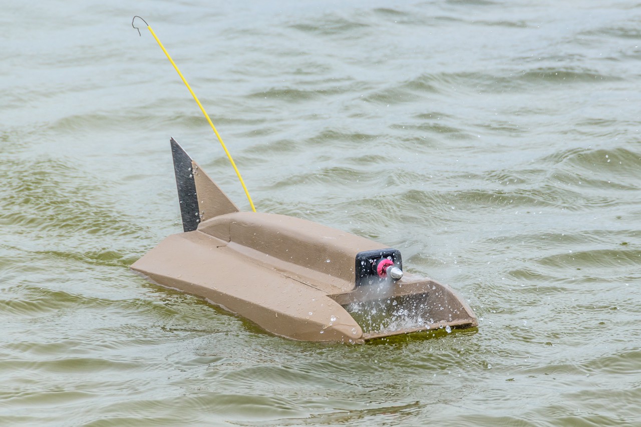
- The water was quite choppy, which will probably always be an issue for this design. As you can see in the photo below, if the prop digs in, the boat suddenly tries to become a submarine.
On the upside, the balance looks pretty good and the rudder worked really well, despite the low speed
![]()
Nevertheless, it was nice to finally see it puttering around. If I had just made it look like a tugboat then I wouldn't have minded that it performed like one ;-)
![]()
-
Last Step: Electronics and Steering
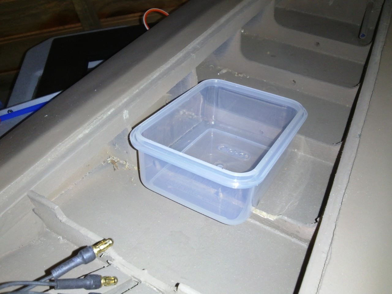
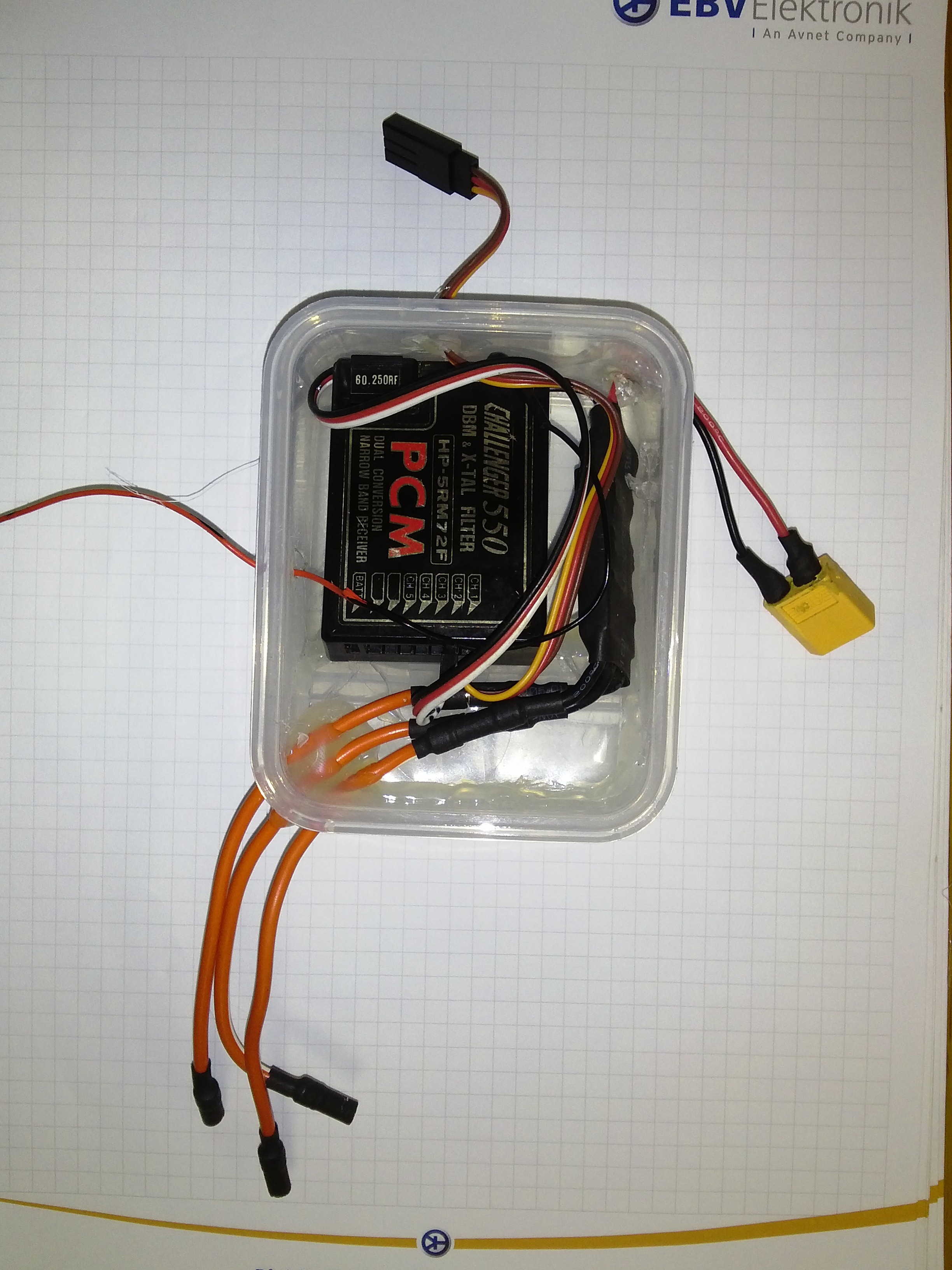
09/16/2015 at 21:53 • 0 commentsI found the smallest snap-shut "tupperware" tub that I could find. Unfortunately, it is just too tall.
![]()
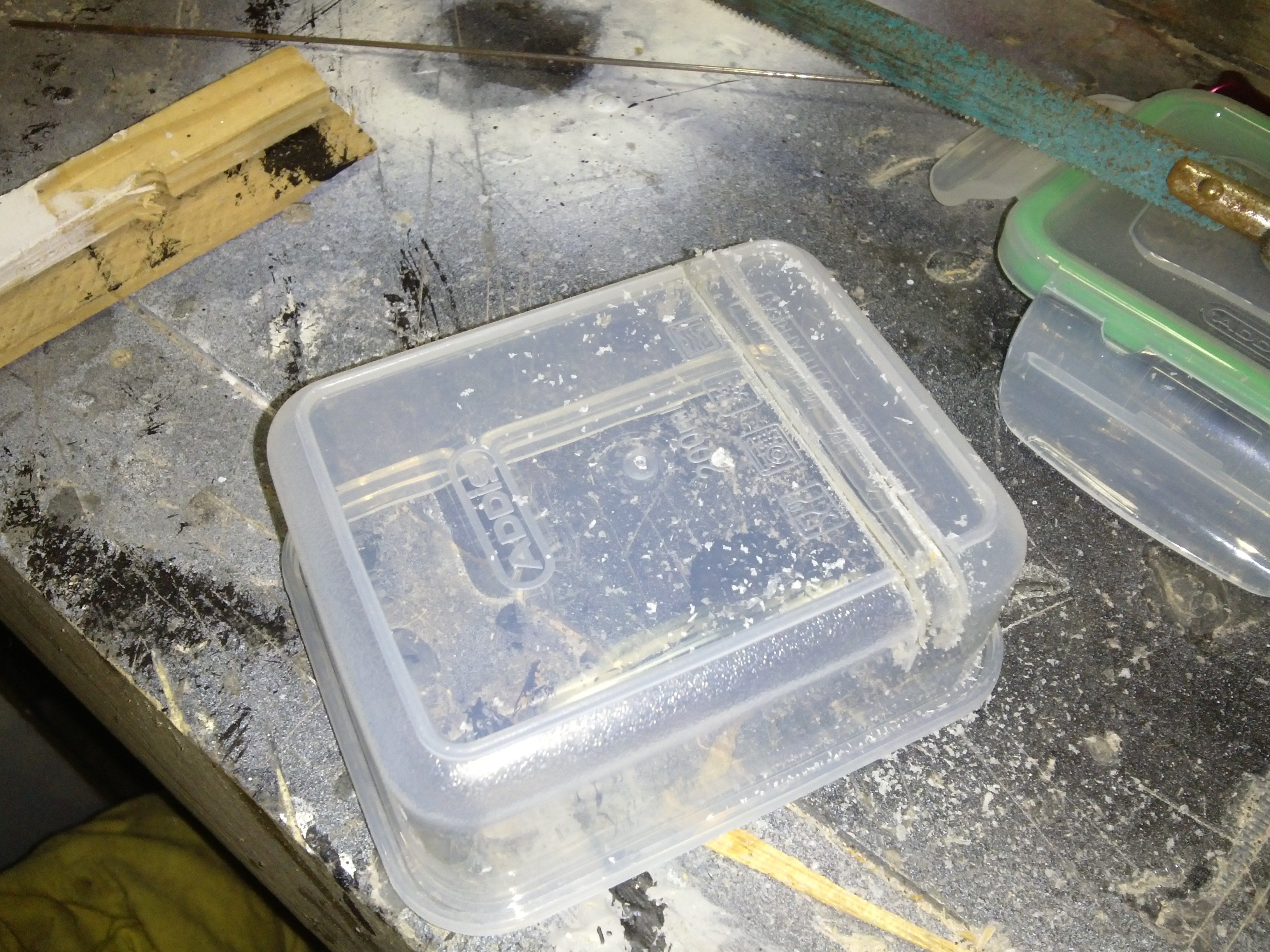
So I made it less watertight
![]()
And then I made it more watertight again, using a bit of scrap plastic and some hot glue.
![]()
It just fits the monster old receiver and the tiny ESC, let's hope they don't interfere with each other. The battery obviously sits outside the box, as does the rudder servo, which is waterproof-enough (I have run the same one in my RC buggy in some pretty grotty conditions, it should be fine)
![]()
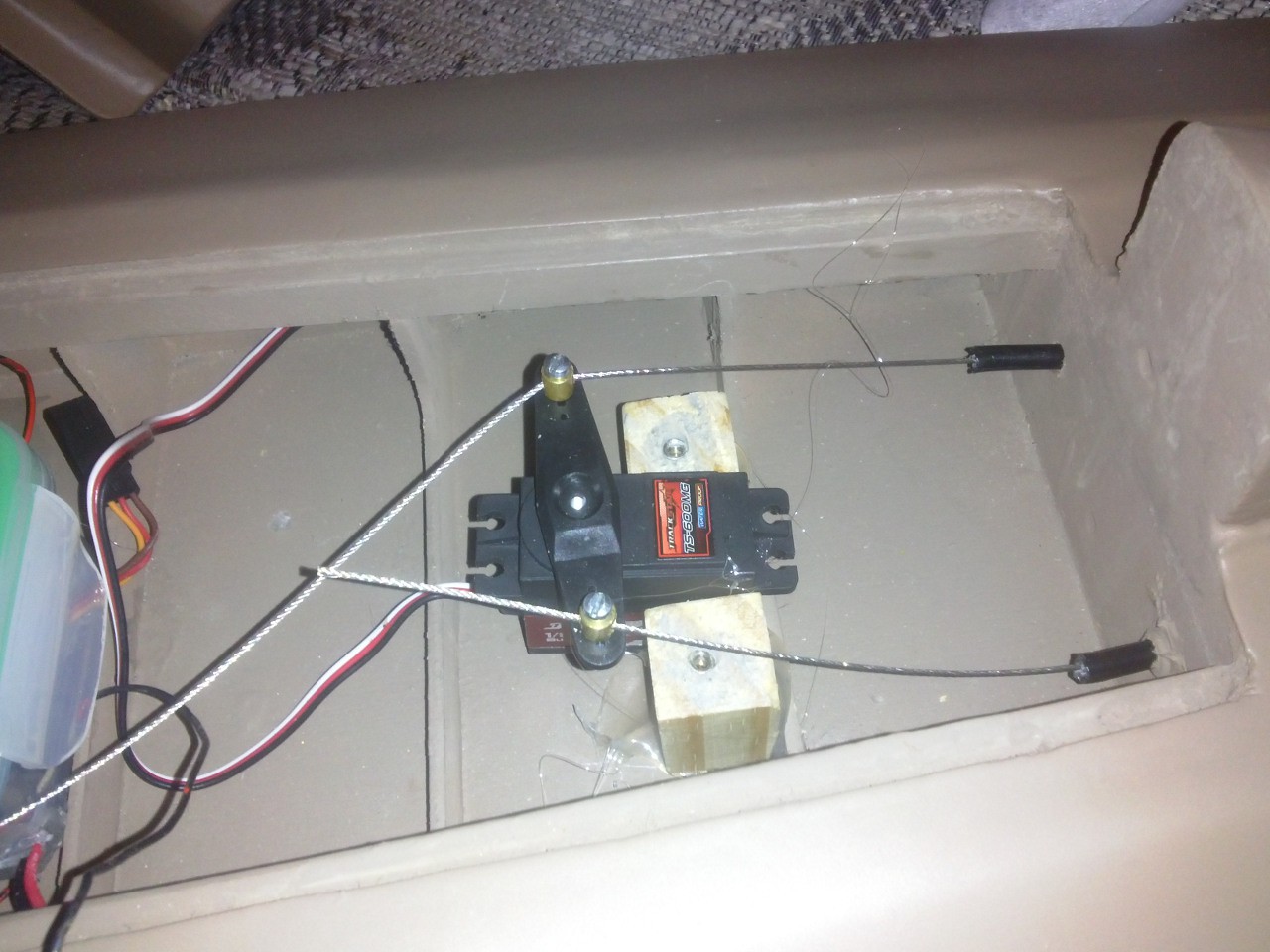
The rudder servo sits between two blocks of wood, hot-glued into the boat. Each of the wood block has a M3 hex standoff epoxied into a hole drilled in it, once everything is finalised I will be able to screw down a little cross-bar to hold the servo in place.
![]()
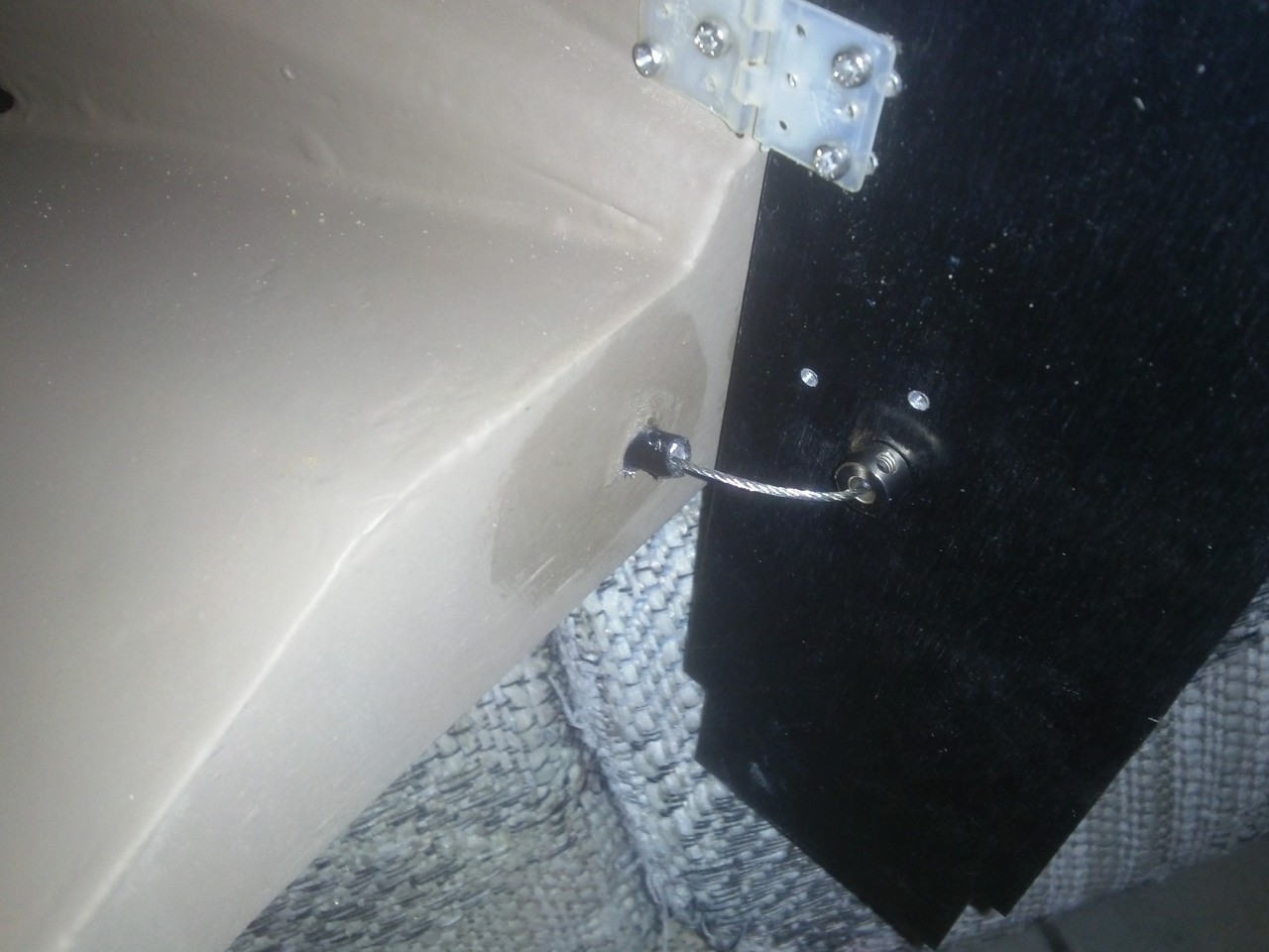
The rudder cable passes through two tubes (bicycle brake cable sheath, but I replaced the actual cable with some thinner, more flexible, stainless steel cable) out to the back. The pull-pull arrangement means that I can use thin flexible cable, since it doesn't have to apply any pushing force.
The cable passes through a hole in the rudder and is held in place one each side with a doodad who's name I can't remember.
![]()
All in all, the boat is ready to go! Unfortunately I loaned out my lone RC battery, so until I get that back the maiden voyage will have to wait. As they say, control without power is boring. Or something.
The next project log will either be "It Sank!" or "It Floated!"
-
Paint!
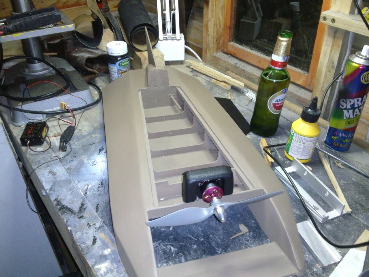
09/06/2015 at 21:40 • 0 commentsThis project log has been an awfully long time in coming, since I was waiting for the boat to get painted. I asked one of the friendly maintenance guys at our office park to spray the boat with "anything waterproof left in the gun after a job", but he really went above and beyond, hitting it first with a few coats of waterproof primer, then some military green-brown, followed by a couple of coats of clear.
Here it is before the clear coat.
![]()
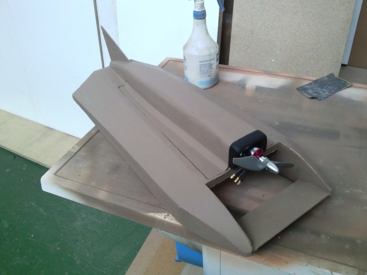
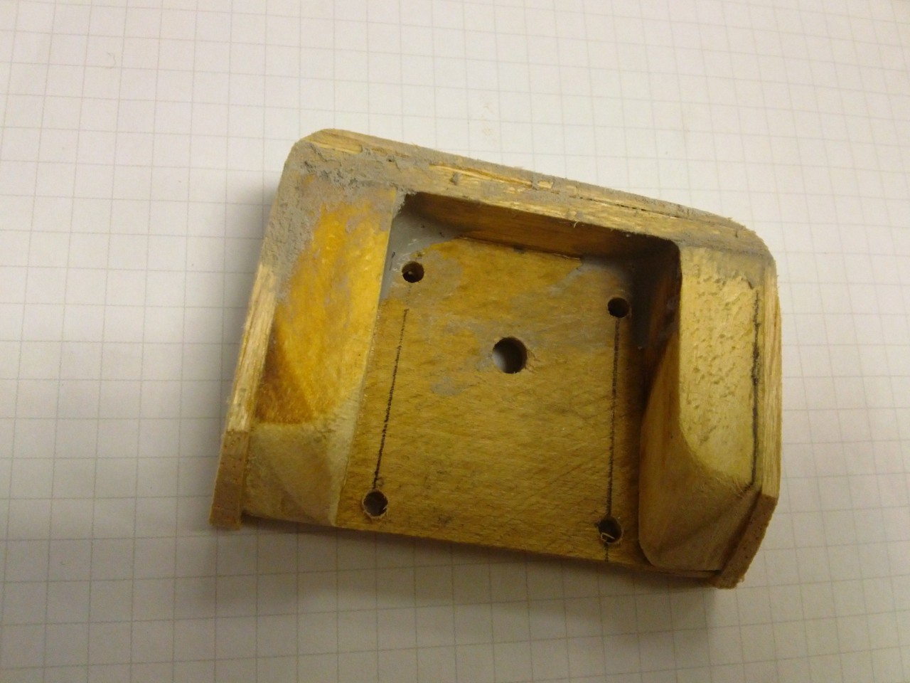
In the previous picture you can see that I also made a little engine-mount/cowl, which was just a few scraps of wood, stuck together and sanded into shape (the backing is some 3mm hardwood of sorts):
![]()
The idea behind this cowl/mount was that I could swap the whole thing out if I later decide to run a motor with completely different dimensions. I also just wanted to disguise the little motor a bit, because it looks kind of silly and "toy-like" to me.
![]()
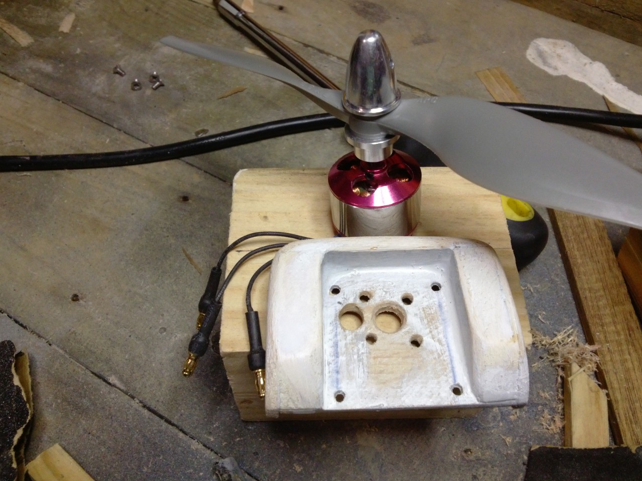
Here is a decent shot of the "cargo" space, you can see how the motor stays behind when the cover comes off. I am really trying to avoid having to detach cables when opening up the boat.
![]()
-
Decking and Touchups
08/18/2015 at 09:10 • 0 commentsI cut some strips of balsa at 45° to use as fillets along the fuselage.
![]()
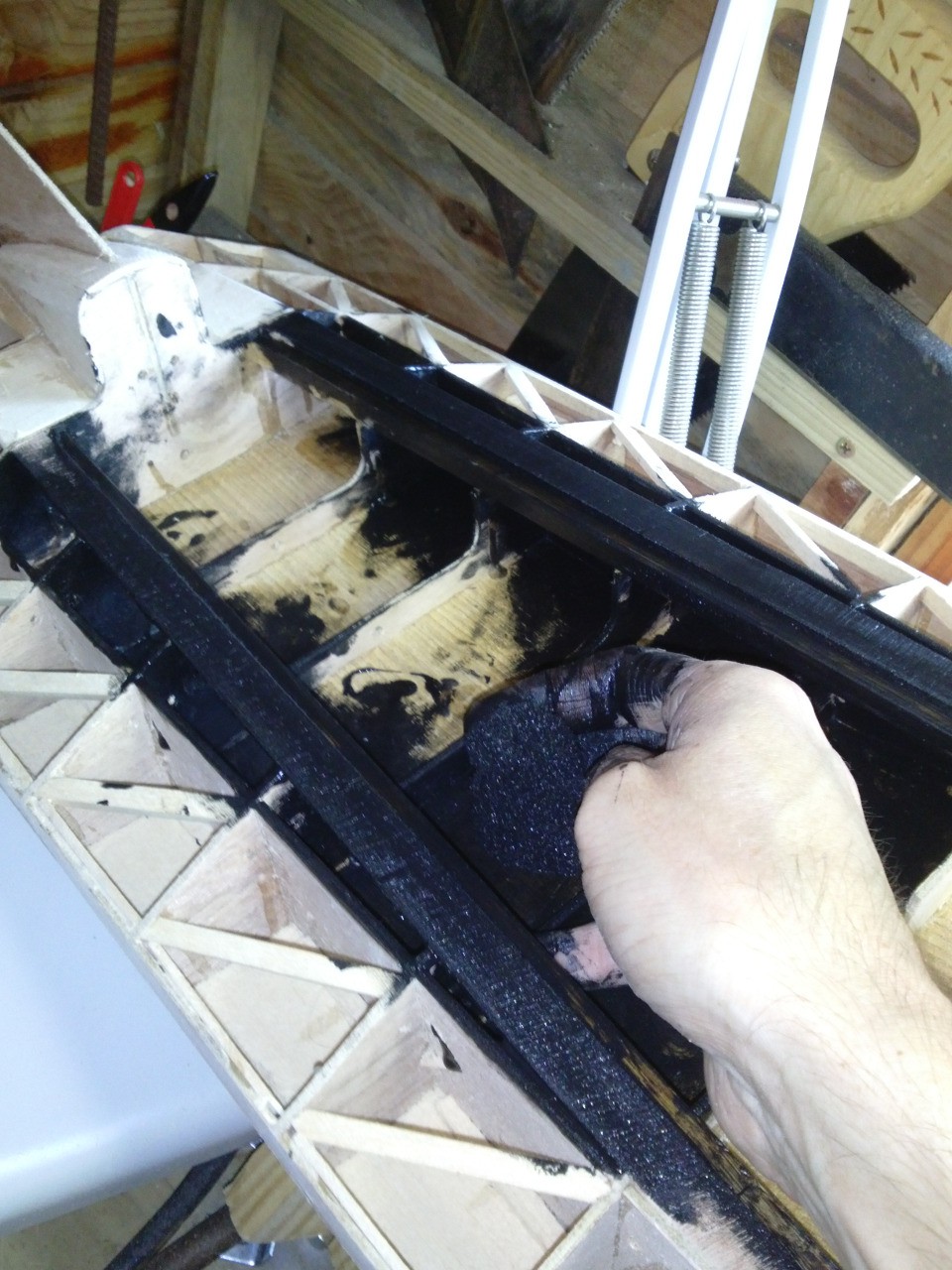
There is a bit of a flaw in my design when it comes to waterproofing the interior, it is almost impossible to get under the stringers. There are twp options, one would be to put little walls in, essentially dropping the stringers straight down, and narrowing the "cargo" space. I didn't want to do that, so I used a sponge to squeeze acrylic paint in everywhere that I could. Not ideal, but it's probably ok. I will fix this in the next design.
![]()
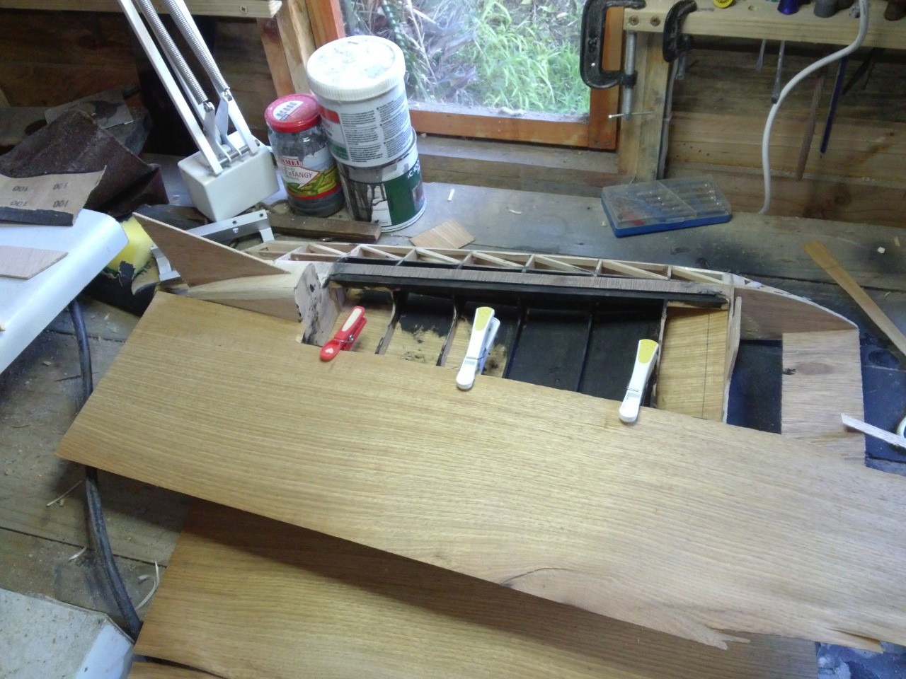
The decking is going to be done with 1mm veneer. I tried to make a 2mm ply out of it, but it ended up being too rigid to conform to the curves. If I built this again I would just use 3mm balsa, but I was insistent on using the veneer that was kindly given to me.
![]()
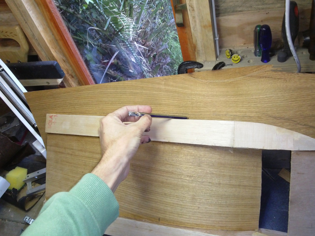
After pegging it to the stringer I made a rough outline from the bottom, so that I could cut it to shape (with a box cutter).
![]()
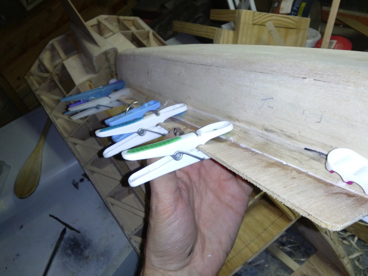
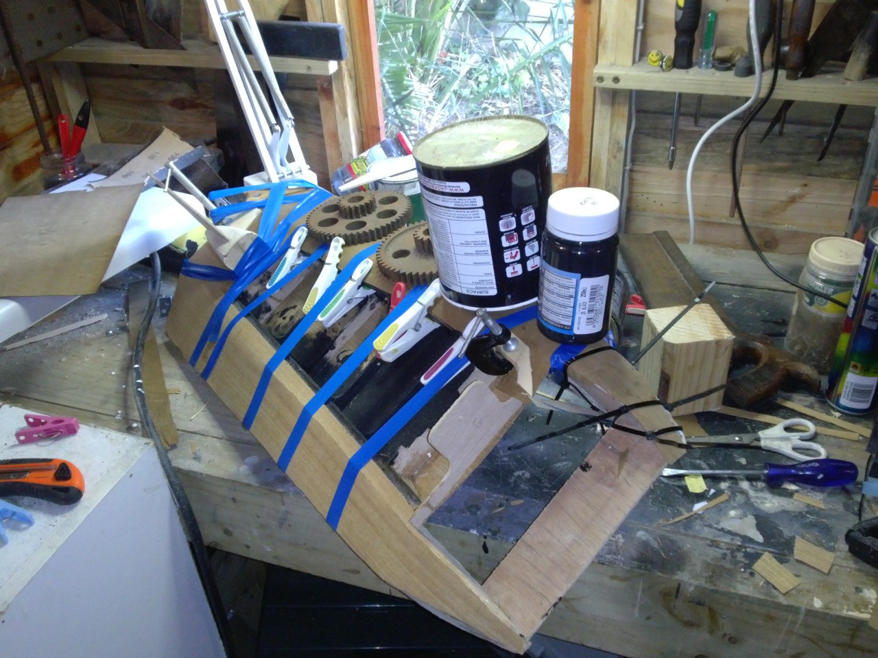
The gluing process involved lots of weights (to keep the middle down), as well as pegs (to hold the edges to the stringers) and electrical tape (to hold the outside edges down) and zip ties (because I ran out of tape!).
![]()
The unwrapped (and trimmed) result is starting to look pretty good, if I say so myself! It looks like something batman would be proud of (once painted black, or very dark gray of course).
![]()
-
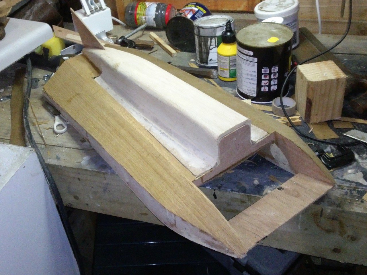
Taking Shape
08/15/2015 at 06:46 • 0 commentsAdded a bunch of balsa bits along the edges, and then sanded them flush, to give some more surface for the cladding to adhere to.
![]()
Gluing 3mm blasa to the bottom of the boat, since I didn't have any suitable clamps I had to get creative with conforming it to the curves.
![]()
On the fuselage I did the same thing, anticipating that I was going to cover it in the 1 or 2 mm plywood.
![]()
It turned out that the corner radii were just too tight for even the 1mm veneer, and it kept splitting, so I decided to clad the fuselage in 3mm balsa instead. The zip-tie holes finally came in handy here.
![]()
Lots of test fitting to make sure the fuselage isn't warping
![]()
![]()
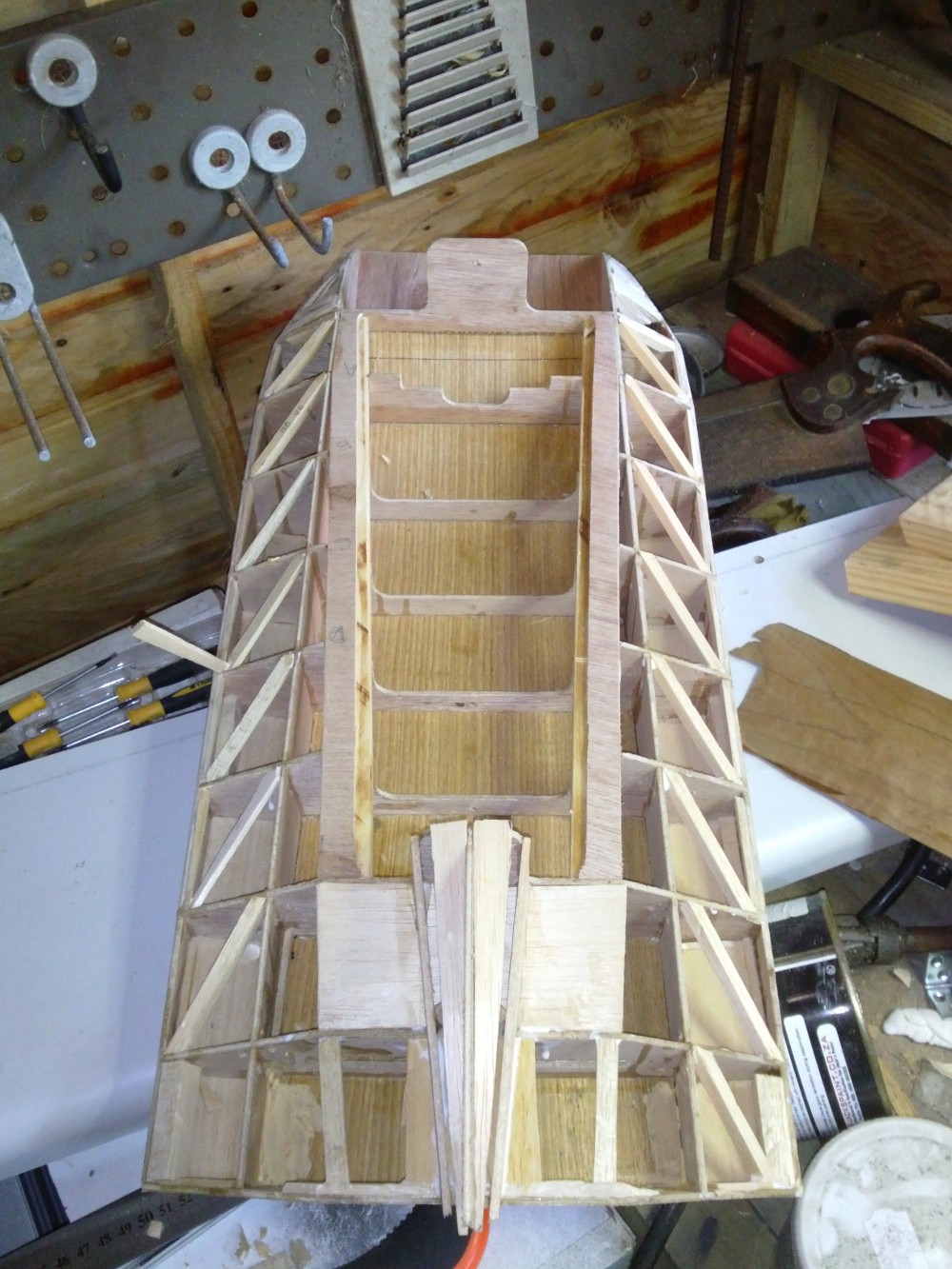
I am stubbornly insisting on cladding the top of the boat with the 1mm veneer, since it was given to me, so I put in some diagonal balsa cross-braces to support it as well as give more gluing area. It would probably be a lot easier to clad the top of the boat in balsa too.
![]()
-
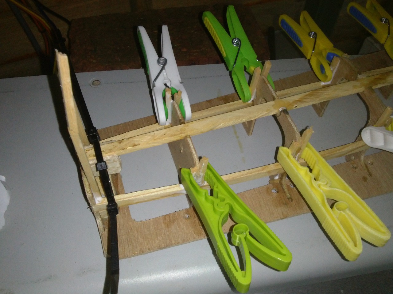
Assembly Continues
08/06/2015 at 14:29 • 0 commentsAssembly has been plodding along. It is a slow process, since the glue takes a while to dry between each step. Among other things I have been:
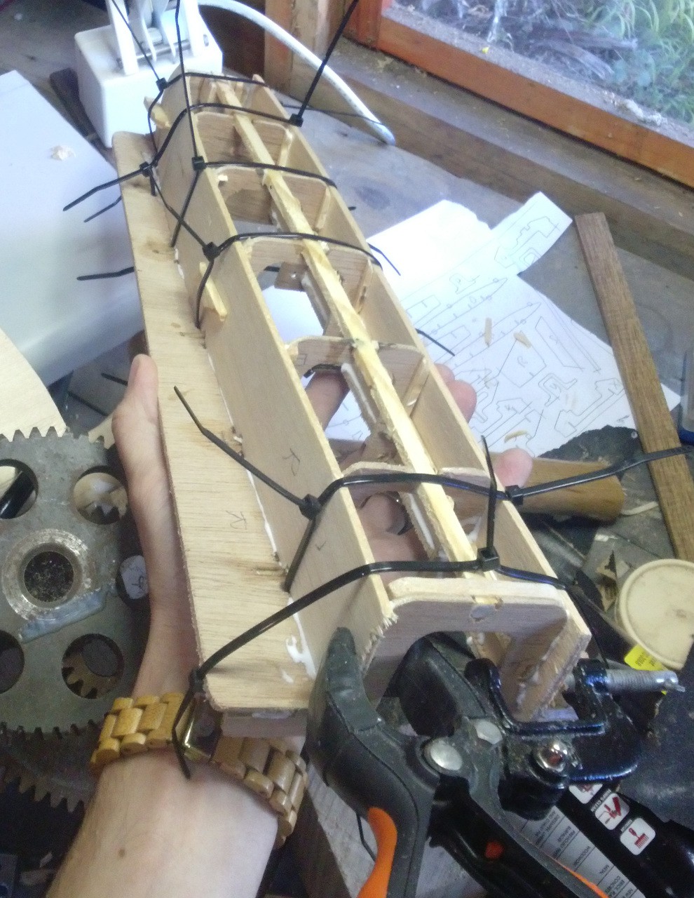
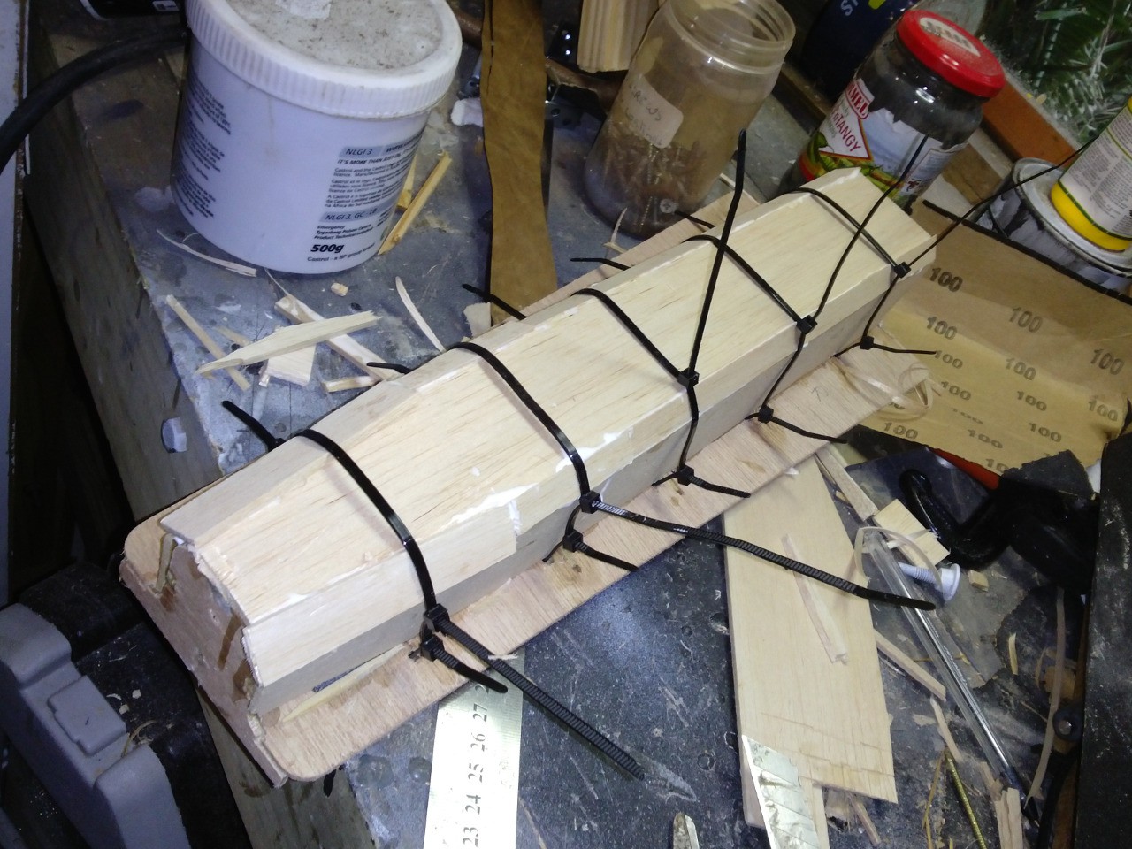
Using cable ties to start bending the curves into the plywood (I considered wetting the plywood, but since its not marine-grade I wasn't sure if that was a good idea or not). I left it like this for a few days and it seems to be working.
![]()
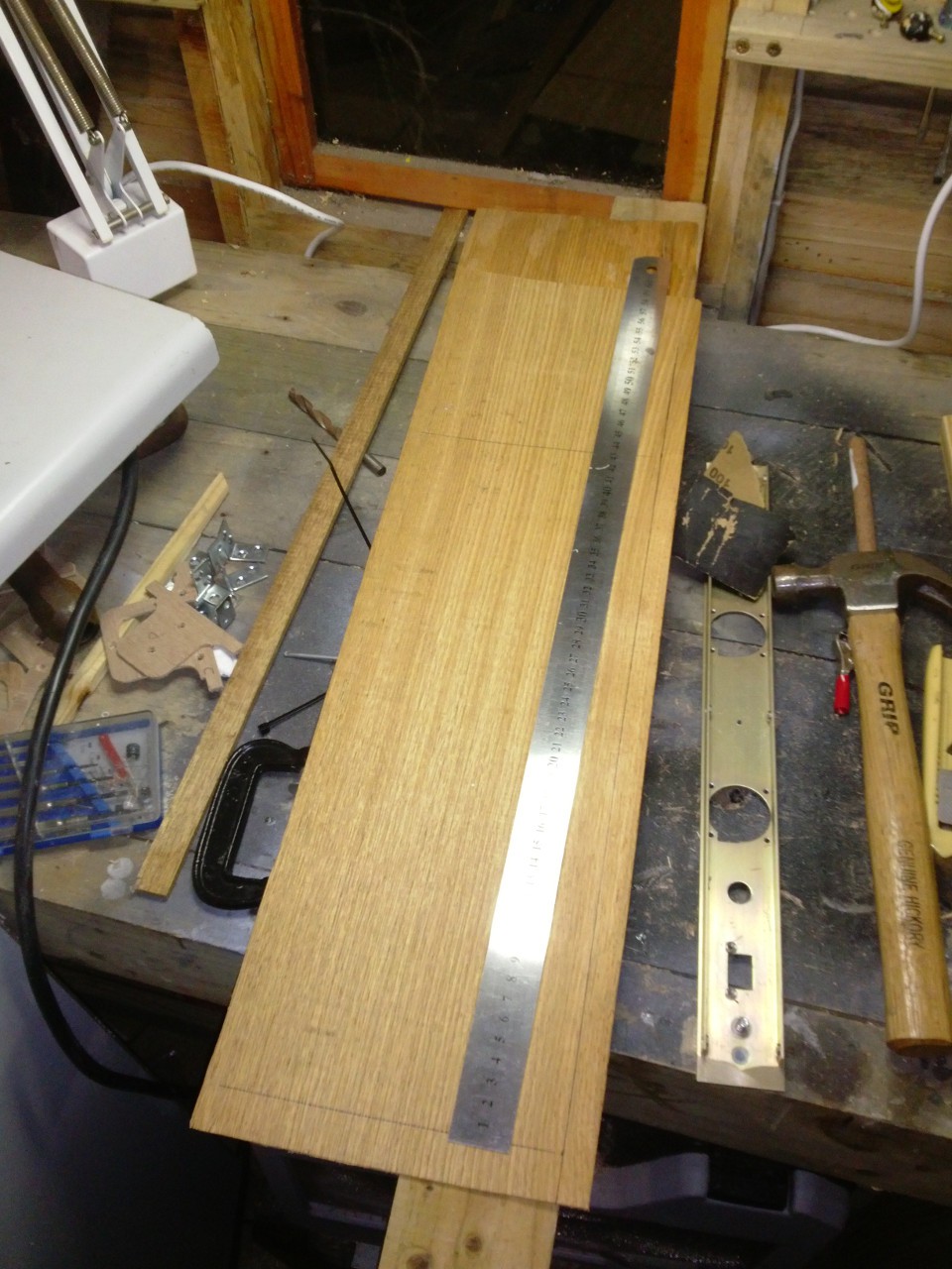
Making 2mm plywood from 1mm oak veneer
![]()
Gluing down the first sheet of oak plywood "skin".
![]()
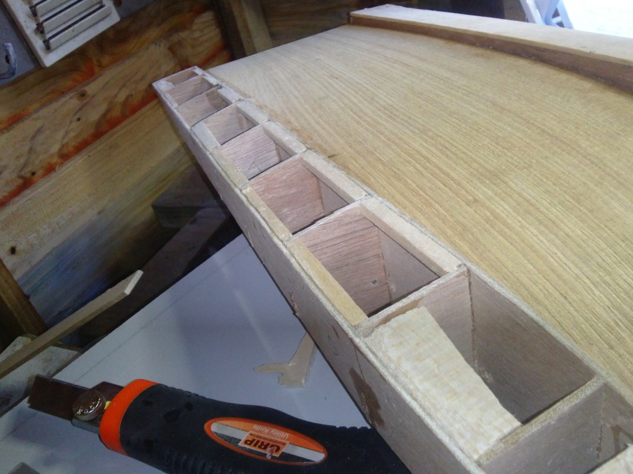
Measuring and installing the 12x12mm beams that form the supports for the lid/fuselage
![]()
-
First Assembly
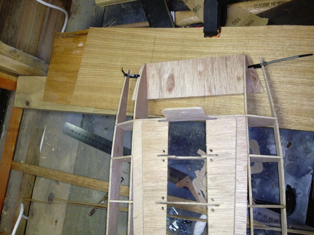
08/03/2015 at 08:39 • 0 commentsFinally we have some real physical progress!
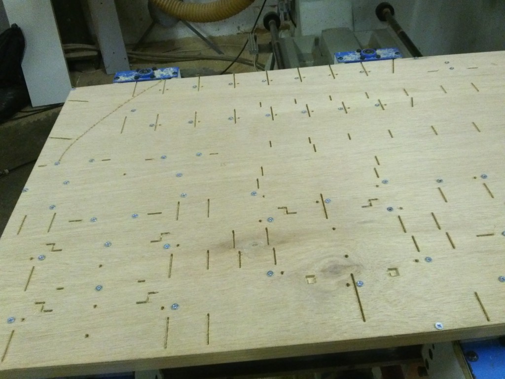
Cutting out such fiddly pieces on a machine designed for cutting big furtniture panels requires an alternative method, so the 3mm ply was screwed down (in many many places) to the wasteboard, which could be held down with the suction cups.
Here you can see the four billion screws and the first cuts (for the 3mm slots)
![]()
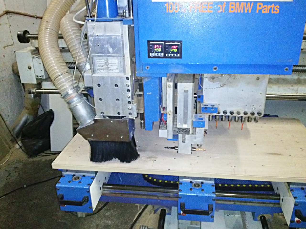
An action photo without any visible action!
![]()
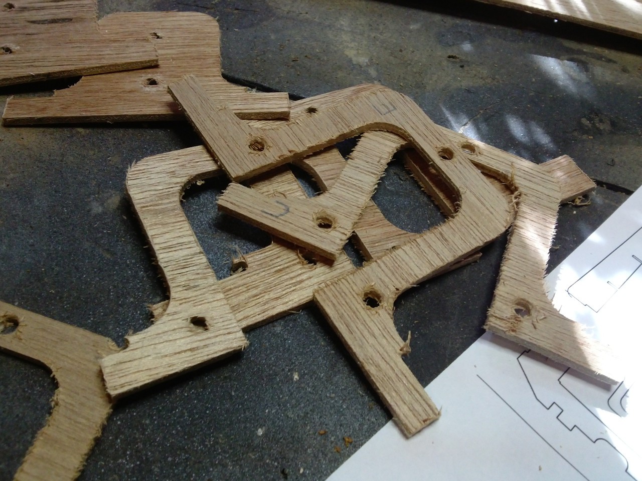
The parts need a bit of cleanup, which is mostly since the plywood is horrible and splintery, nothing that a few minutes with some sandpaper couldn't solve.
![]()
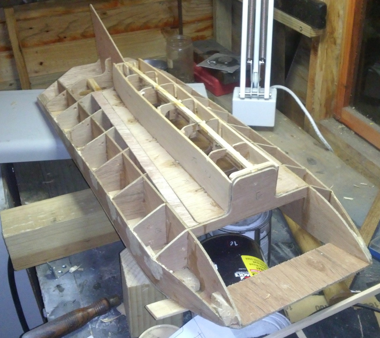
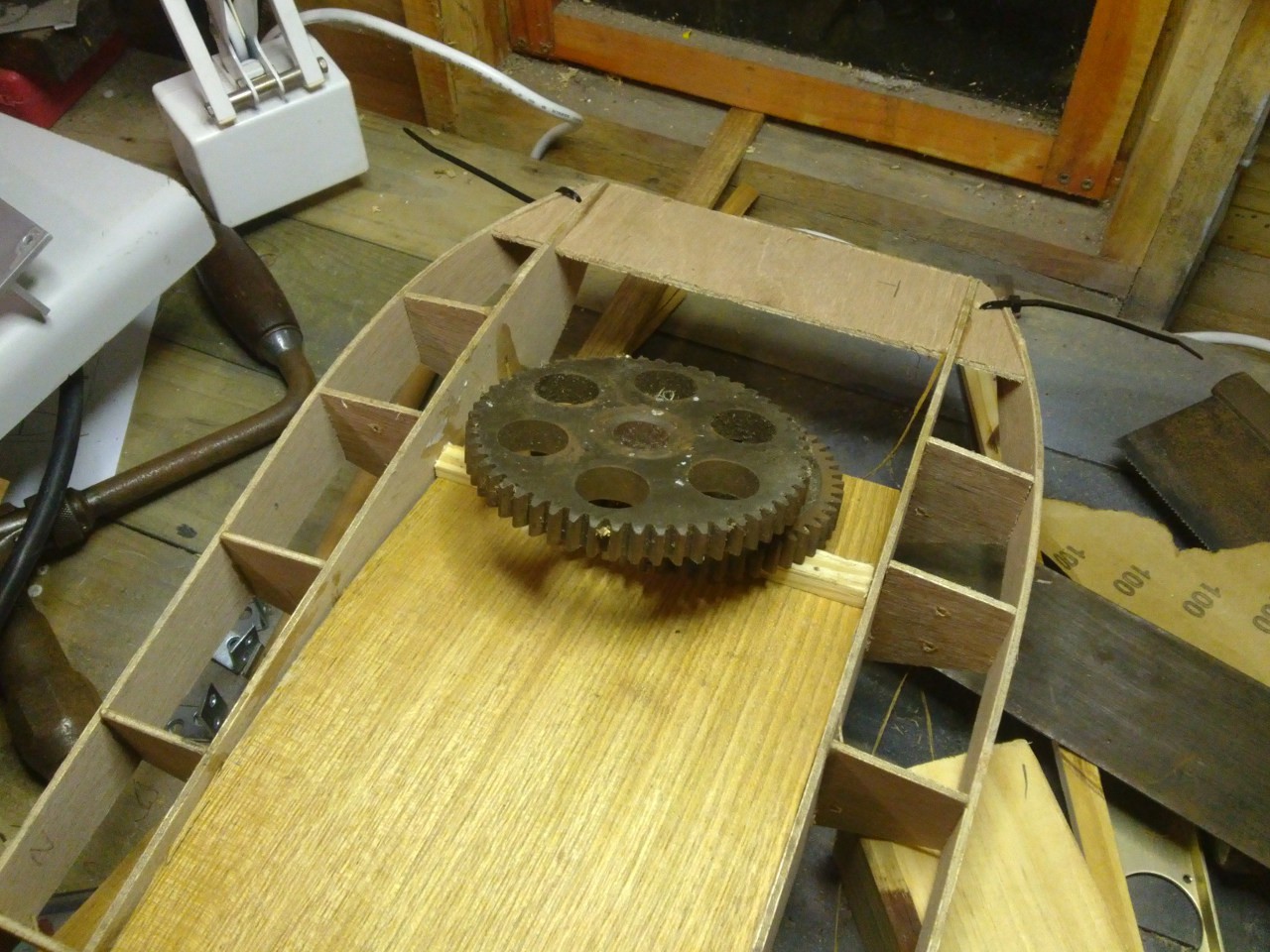
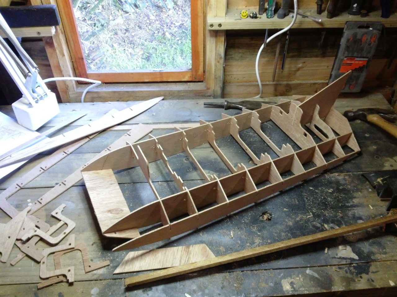
First glue-less assembly looks good, this design goes together very easily.
![]()
However, once I assembled with glue I discovered a problem, which is probably pretty evident in the next photo. Despite my best efforts, the whole thing kinda "paralleogrammed" and I ended up with a boat which would be suitable for NASCAR and not much else. This is my own stupid fault, I should have designed a piece which slotted in the third axis, to prevent this kind of skewing.
![]()
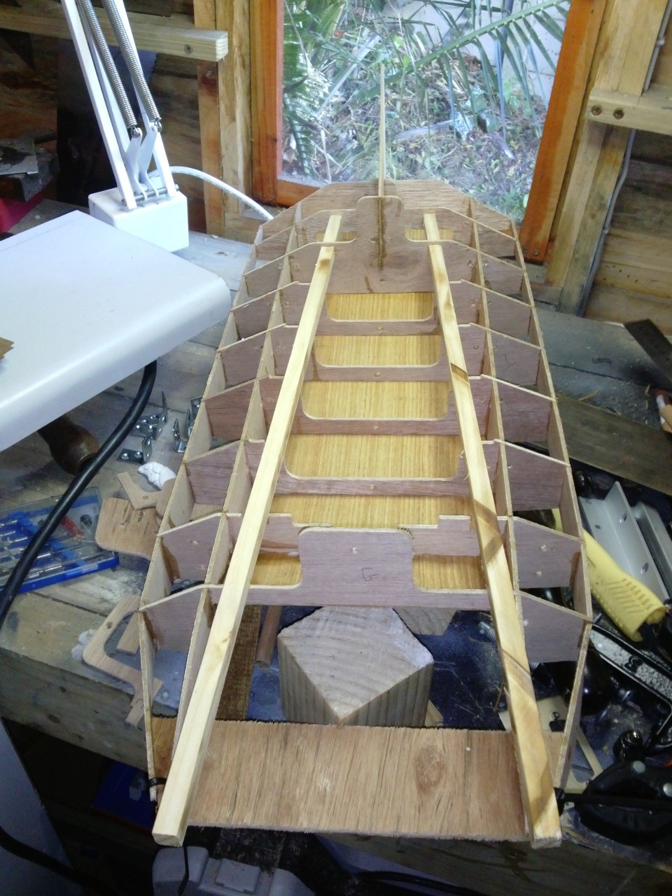
Some force and a craft knife got me back to square one.
![]()
-
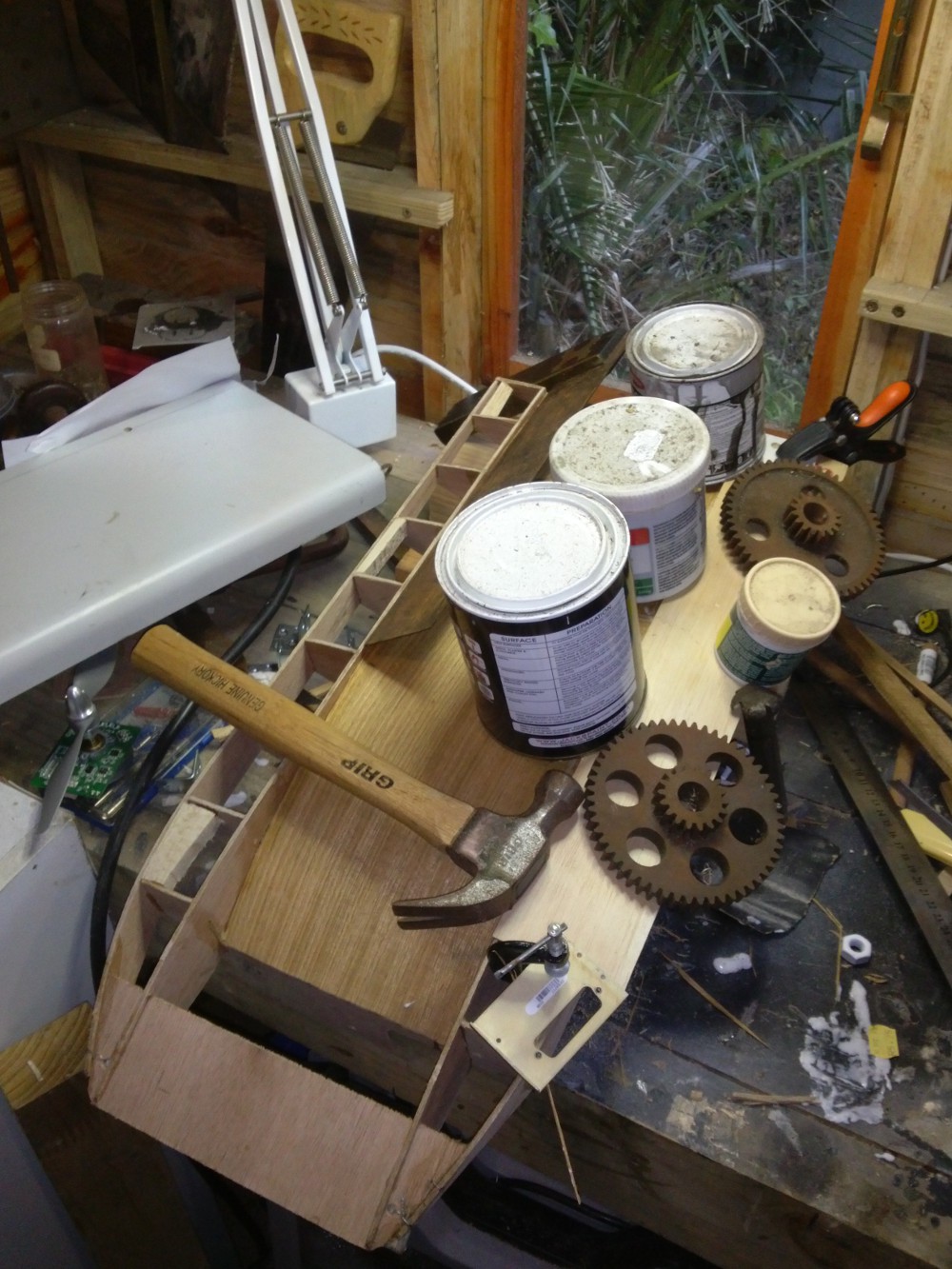
Prop Mount
07/26/2015 at 19:59 • 0 commentsNot much progress to report, but I did manage to get hold of a collet (something like this) from my local hobby shop to attach a prop to a 6mm shaft. The prop was salvaged, along with a collection of others, from my late granddad's garage. I have fond childhood memories of the cool RC planes that he and my uncle built from scratch, he would have loved this project.
The prop seems to generate an appreciable amount of thrust, pulling roughly 600mA at 24V (14.4 W), but I am still unsure whether it will be enough.
My reading on electric plane motor choice (since no one seems to make boats with props and talk about their motor choice) says that 60W per pound is bare minimum. Even if an airboat only needs a quarter of the power of a plane (that sounds boring), I don't see my boat coming in at half a kilo. If anyone has some actual numbers for me to work with, I'd appreciate it.
![]()
Along with the prop and things I also got the radio I think I will be using; with "1991 Style" technology and five channels it is light years more advanced than any of the transmitters I am using for my RC cars.
![]()
-
Motor Control
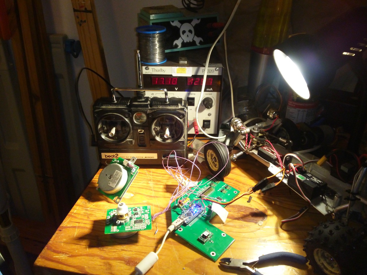
07/23/2015 at 23:56 • 0 comments![]()
Real life got in the way for my friend doing the CNC-cutting, so there are still no parts. In the meantime I decided to get stuck into the motor control.
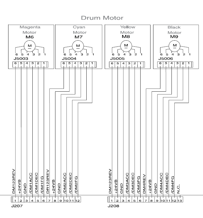
I pulled these motors from an HP Color LaserJet 3000 series printer a few months back. After some digging I discovered that googling "HP Printer <number> service manual" invariably brings up some pretty decent documentation.
Since I really wasn't sure whether the motor would even have enough power for my purposes, I whipped up a quick prototype with an Arduino Nano clone to test it out. If I end up using the motor I will build a little board and port the code to an ATTINY85 or similar.
![]()
The control signals are pretty simple (I am using 5V logic, which it seems happy with)
- /ACC requires a PWM for speed control
- /DEC is a "brake" (I think of it as an enable pin)
- REV controls direction
- FG is an output which can be used for closed-loop control
The biggest nuisance is that the motors require 24V DC, not a great voltage for standard RC batteries.
I have it running off a bench supply at 24V at the moment, the Arduino is sitting on an old board left over from another project, which works out well, since it has a 5V switch-mode supply on it, to feed the Nano and the RC receiver.
The Nano listens for standard RC servo signals from the receiver (this post was handy) and sets the pins for the motor accordingly. I had to increase the PWM frequency of the Arduino and found this TimerOne library made it easy-peasy.
I have some video of the motor running, but my internet is being ridiculously slow, I will upload it when possible, so that you can all bask in its glorious whine. I can't say for sure yet whether the motor will work for the boat. It spins with enough torque that the 6mm shaft burns my fingers when I try to stop it, but my finger-heat to thrust calculations are a bit rusty. Once I figure out how to mount a prop I will know more (or just lose my fingers all together).
UPDATE: here is the video, as filmed with a shaky low-resolution potato
The code is attached below, in case anyone is interested
// Jason Suter 24/07/2015
// Built for https://hackaday.io/project/6660-airscrew-driven-rc-boat
// Code designed to control a brushless DC motor from an HP printer (RK-0934 or similar)
// RC signal interpretation from this blog post http://rcarduino.blogspot.com/2012/01/how-to-read-rc-receiver-with.html


#include <TimerOne.h>


#define THROTTLE_SIGNAL_IN 0 // INTERRUPT 0 = DIGITAL PIN 2 (I think)- use the interrupt number in attachInterrupt
#define THROTTLE_SIGNAL_IN_PIN 2 // INTERRUPT 0 = DIGITAL PIN 2 - use the PIN number in digitalRead
#define NEUTRAL_THROTTLE 1500 // this is the duration in microseconds of neutral throttle on an electric RC Car
#define DEADZONE 50 // microseconds of deadzone
#define KILLTIME 50 // if there is no pulse received after this duration (milliseconds), then kill the motor


int stopPin = 3;
int pwmPin = 9;
int revPin = 7;

volatile int inputPulseLength = NEUTRAL_THROTTLE; // volatile, we set this in the Interrupt and read it in loop so it must be declared volatile
volatile unsigned long ulStartPeriod = 0; // set in the interrupt
volatile unsigned long killStartPeriod = 0; // set in the interrupt
volatile unsigned long invertedPulseLength = 0; // micros of new pulse we need to put out (3000 - lastPulse)
volatile boolean bNewPulse = false; // set in the interrupt and read in the loop


// the setup function runs once when you press reset or power the board
void setup() {
  //timer setup
  Timer1.initialize(300);
  Timer1.pwm(9, 512);

  // initialize digital pin 13 as an output.
  pinMode(stopPin, OUTPUT);
  pinMode(pwmPin, OUTPUT);
  pinMode(revPin, OUTPUT);

  pinMode(13, OUTPUT);

  digitalWrite(stopPin, true);

  attachInterrupt(THROTTLE_SIGNAL_IN,calcInput,CHANGE);

  Serial.begin(9600);

}


// the loop function runs over and over again forever
void loop() {


    if (bNewPulse) {
      int pulseDelta = min(max(abs(inputPulseLength - NEUTRAL_THROTTLE),0),400);
      int newPwm = map(pulseDelta,DEADZONE,400,0,1023);
      Timer1.pwm(pwmPin, newPwm);

      if ((inputPulseLength > NEUTRAL_THROTTLE) && (pulseDelta > DEADZONE)) {
        //Serial.print("forwards");
        //Serial.println(pulseDelta);
        //Serial.print("newpwm");
        //Serial.println(newPwm);
        digitalWrite(revPin, false);
        digitalWrite(stopPin, false);
      }
      else if ((inputPulseLength < NEUTRAL_THROTTLE) && (pulseDelta > DEADZONE)) {
        //Serial.print("backwards");
        //Serial.println(pulseDelta);
        //Serial.print("newpwm");
        //Serial.println(newPwm);
        digitalWrite(revPin, false);
        digitalWrite(stopPin, false);
      }
      else {
        //Serial.println("stop");
        digitalWrite(stopPin, true);
        Timer1.pwm(pwmPin, 0);


      }
      bNewPulse = false;

    }

    if ((millis() - killStartPeriod) >  KILLTIME) {
      digitalWrite(stopPin, true);
      Timer1.pwm(pwmPin, 0);
      //Serial.println("stopped - signal lost");
    }


}


void calcInput()
{
  // if the pin is high, its the start of an interrupt
  if(digitalRead(THROTTLE_SIGNAL_IN_PIN) == HIGH)
  {
    // get the time using micros
    ulStartPeriod = micros();
    killStartPeriod = millis();
  }
  else
  {

    // if the pin is low, its the falling edge of the pulse so now we can calculate the pulse duration by subtracting the
    // start time ulStartPeriod from the current time returned by micros()
    inputPulseLength = (int)(micros() - ulStartPeriod);
    ulStartPeriod = 0;

    // tell loop we are outputting a new pulse
    bNewPulse = true;
    //Serial.print("new pulse ");
    //Serial.println(inputPulseLength);

  }
}