Ossum
Ossum-
Preparing for Cutting
07/15/2015 at 08:15 • 0 comments![]()
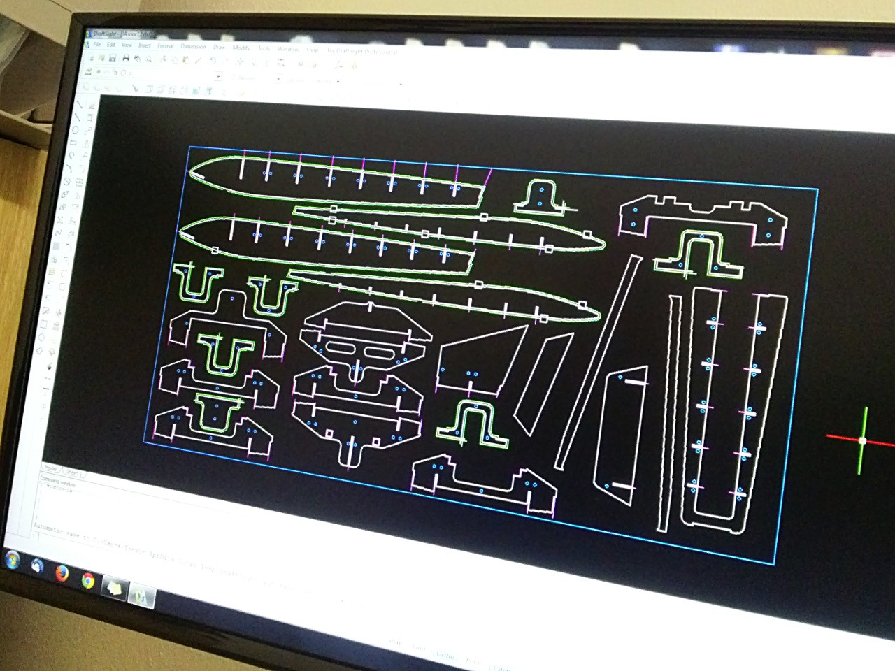
Last night I met up with my friend who is going to cut out the profiles on his CNC machine. His machine is a vintage monster (V. Alberti Edit 3000), usually used to cut out large pieces for his furniture business, not really suited to the fiddly work I was presenting. There is a limit of 800 lines of g-code in a program, which means that the the splines and crazy curves that SolidWorks generated when I converted the drawing to DXF needed to be optimised.
After a couple of hours of work with DraftSight we had approximated all of the splines with radii and generated about half of the toolpaths. The majority of the shapes will be cut out with a 6mm cutter, while the notches and 90' corners will use the 3mm cutter. There are holes all over the show which will be used to screw the profiles down the the wasteboard beneath, since the CNC machine only has suction cups for holding large boards.
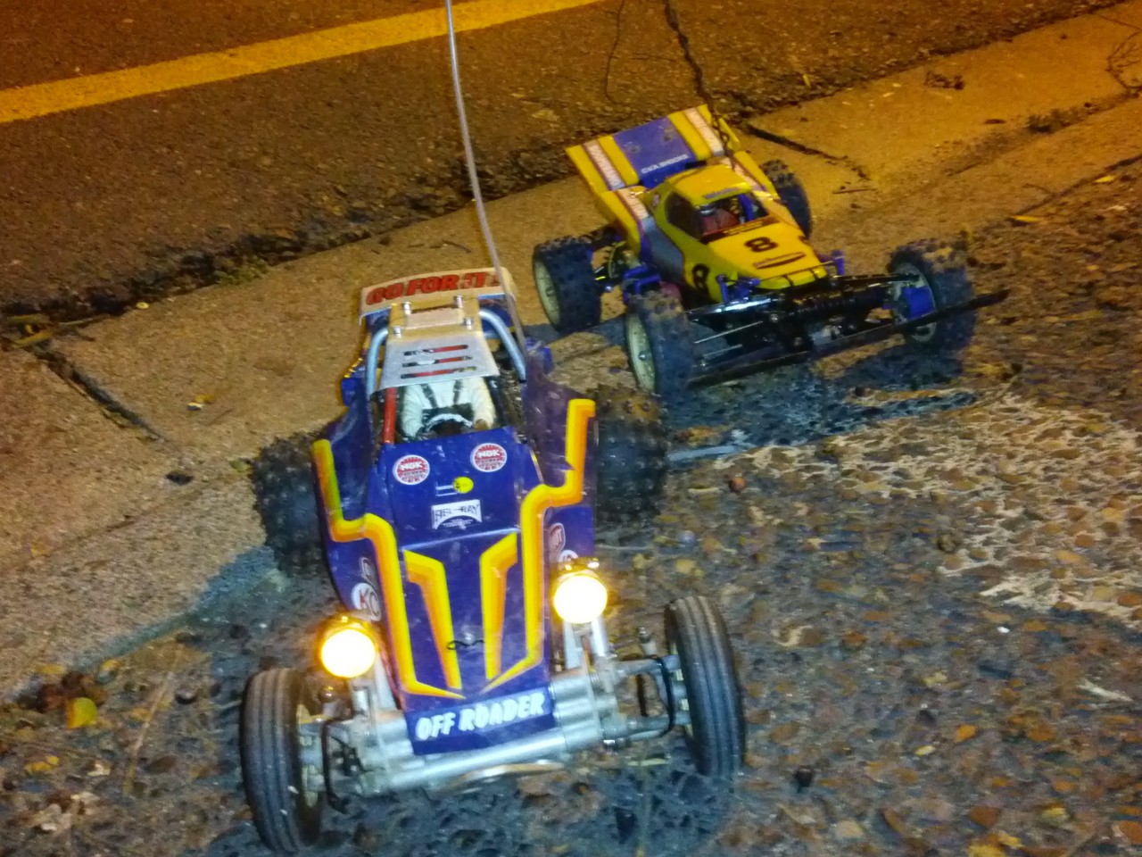
There is still some work to be done before the program is ready to run, but it is close! I'd kept my poor friend at work until 10pm, so it was time to release him, but not before we took our vintage RC cars out for a run in the street outside the factory. These little beasties were actually what got us both back into the RC hobby, so the boat owes something to them.
![]()
-
Making a Cutting Sheet
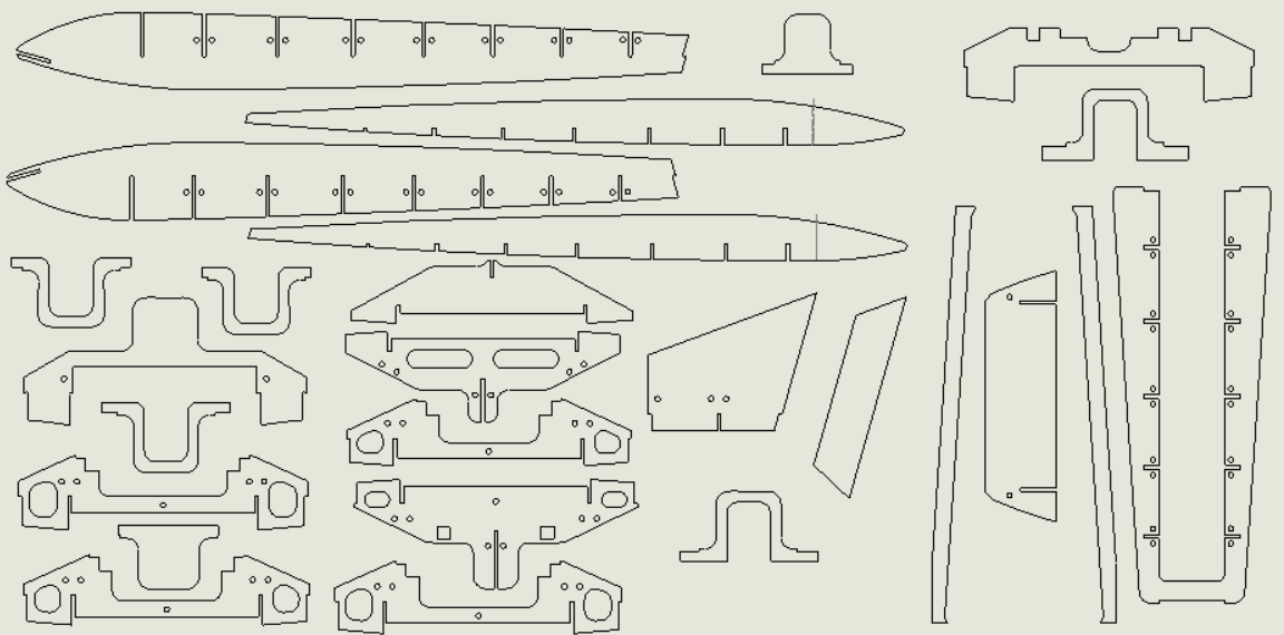
07/13/2015 at 23:02 • 0 commentsTonight I spent a few hours (nothing is ever quick when it comes to CAD assemblies with interdependent pieces) doing some final tweaks on the design and preparing it for cutting. If all goes according to plan I will be cutting the pieces tomorrow night, then things will really start to take shape!
Once I have proved that the design goes together nicely, I will share the DXF files for anyone who is interested.
They have been laid out to fit on a 1200x600mm piece of 3mm plywood.
This design is actually far better suited to laser cutting, what with all the tight inside diameters, but I have a generous friend who will do it on his CNC router for the price of takeaways, so I'm going to give that a shot first.
![]()
-
More CAD work, the end is nigh
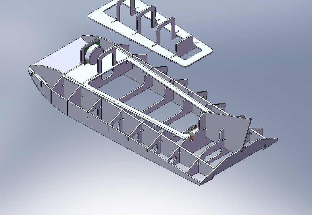
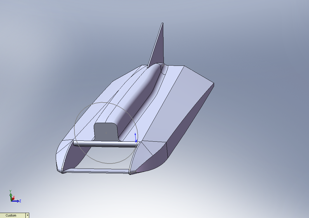
07/07/2015 at 23:40 • 0 commentsAfter staying up altogether too late I am getting very close to a complete design of all the profiles that will form the hull shape.
The thing that has been giving me sleepless nights (literally, I think I have a problem letting go of projects) was how to make the "fuselage" removable in order to get to the electronics within. I think I have achieved that now, while maintaining what I hope will be an easy to assemble design.
![]()
The "lid" will rest on a 12x12mm stringer of balsa or similar, this prevents it falling in to the cavity. I also made sure that there would be suitable (I hope) edges everywhere where I will be glueing down the "skin" wood.
![]()
-
CAD work
07/06/2015 at 20:31 • 0 commentsI found the original plans here. I tried to contact the site owner to see if he had ever seen one built, or knew where the plans came from, but so far have received no response.
So far I have spent far more hours than I would like on digitizing the old plans. I have never attempted a model with so many strange lofted curves, and Solidworks 2007's surface modelling is sketchy, if you'll excuse the pun. Rumour has it that the recent versions have some rather fancy tools for unfolding surfaces, but I don't have access to those.
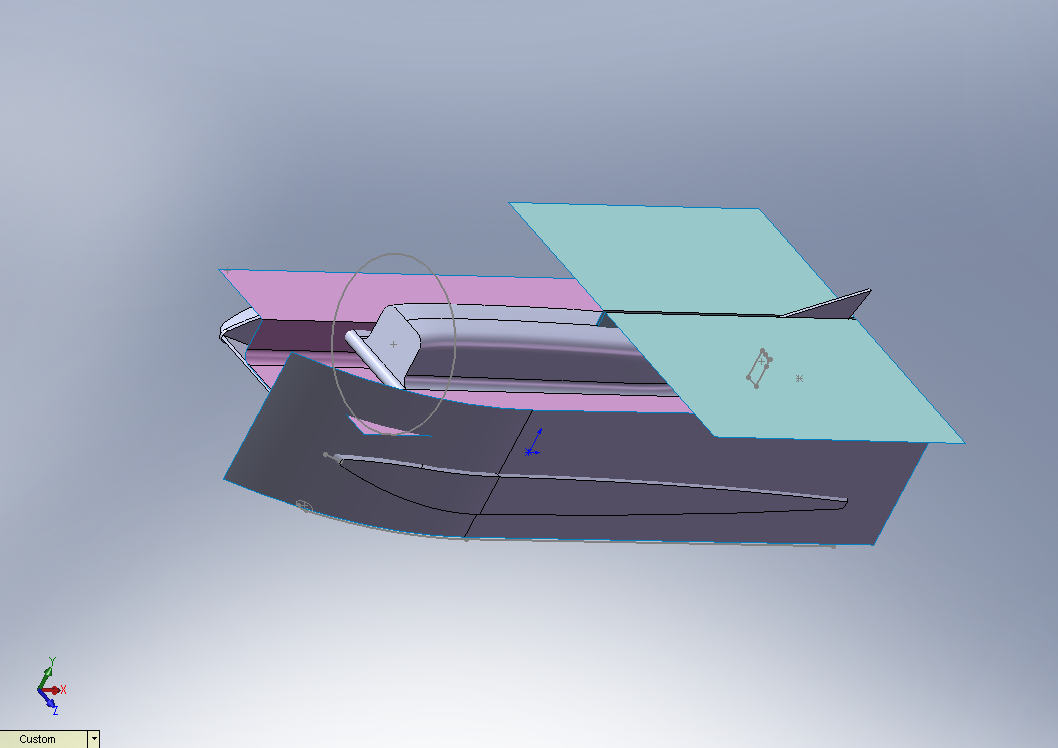
In the end I decided to model the whole boat as a solid, and then use a multitude pf planes and carefully shaped surfaces to cut it into profiles.
The "sheet metal" tool was able to unbend one or two curved surfaces, but I anticipate skinning the whole boat with hand-cut 1mm ply, so I am not going to fight with it to do the trickier ones.
![]()
These surfaces are used as guides later on.
![]()
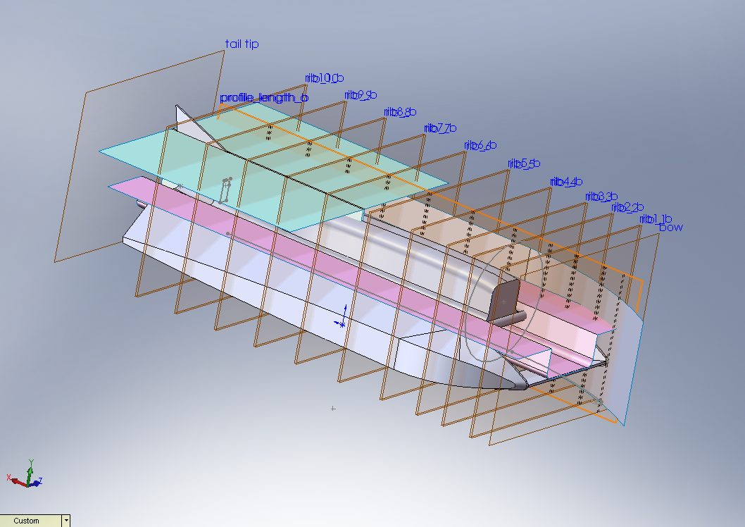
The multitude of planes are used to define where the various profiles will be. Since all the dimensions are dependent on these planes, I should be able to change the thickness of the stock without breaking the whole assembly. Then again, maybe not.
![]()
Each profile is a separate part, made by inserting the 3D solid into a new part and then cutting away the unwanted material, using the various planes and surfaces as guides.
![]()
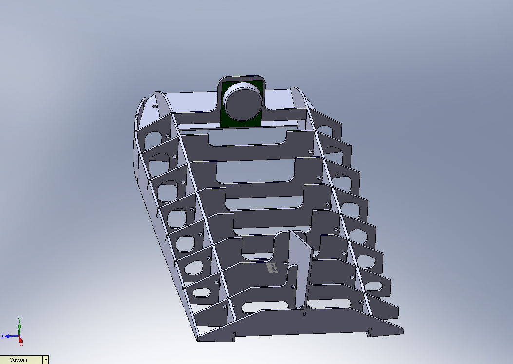
I am currently beating my head against a wall, trying to model the "fuselage" as a detachable cover that fits into the available space while also being easy to fabricate and assemble.
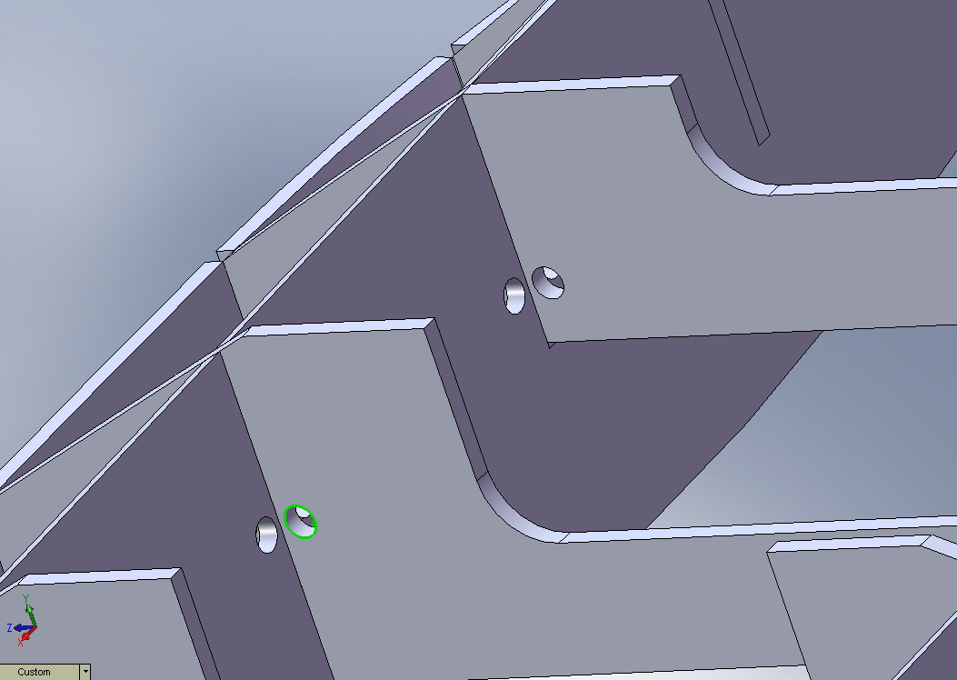
You will see little holes at the intersection of almost all of the profiles, the idea is that they will be handy points to screw the plywood down when CNC cutting, as well as being used with zip-ties to hold the whole assembly together while glueing. It feels very clever right now, but only time will tell.
![]()