 Bob Baddeley
I quickly threw together a sample enclosure for a cell to see if the size was about right for the installation and for usability. I settled on 9"x9"x3", which allows ample room for a large button, lengthy description, and a sizable area for the actual mechanics. It was a big hit with the museum curator, who loved the size and used it to block off the area in the museum where it will go to get a sense of how big it will be and what it will look like.
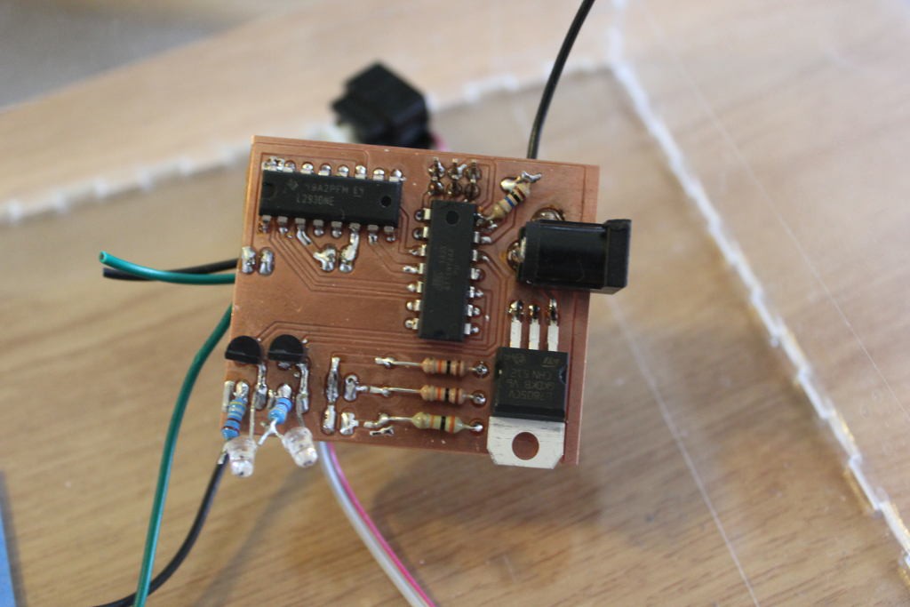
I also etched the first revision of the PCB to test the motor controller, ATTiny, mosfets, power supply, and capacitive touch. I learned quite a bit and have some good changes in mind for the next revision.
- Capacitive touch works great, through acrylic with no problems.
- ATTiny works great. Easy to program.
- Limit switches work great. I'm using a single pin and checking the ADC value with different resistors for each switch, so I can tell which one was pressed with only a single pin. The next revision will allow up to 4 switches.
- MOSFETs work great.
- Motor controller works, BUT the motors require a huge current to start, and it's browning out my electronics. I've decided that rather than a single supply and a regulator, I'll have a +5 and +12 bus and no regulator on board. The supply will be done with an ATX supply, and the higher current will be necessary because I imagine a common use will be little kids pressing every button at once.
- The power plug doesn't make sense any more.
- I am adding the ability to do servos as well as motors. Not simultaneous, but in case a cell needs a servo instead of a DC motor, this should work.
- I'm switching a MOSFET from 5V to 12V. This one will be dedicated to an LED strip which indicates a cell is on. I couldn't find 5V LED strips.
Discussions
Become a Hackaday.io Member
Create an account to leave a comment. Already have an account? Log In.